


SpectraLink 6300 MCU: Facility Preparation
PN: 1725-36122-001_M.doc
20
Required Materials Provided by Customer
Required hardware
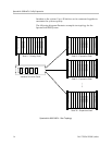
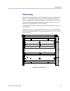
Rack The shelves are designed to fit into a 19” mounting rack.
Each shelf measures 15” high x 19” wide x 9” deep, and weighs
approximately 35 pounds fully loaded.
Backboard Space As an alternative to rack mounting, the shelves
can be wall mounted to 3/4” plywood securely screwed to a wall.
Screws Required to mount the shelves to the wall, or to secure it
in the rack. For wall mount, six #10 5/8” panhead wood screws
(or similar device) are required. For rack mount, screws required
are determined by the rack requirements; typically 10-32 or 1/4-
20. For multi-shelf systems, four 1.75” #8 panhead wood screws
are required to secure the Intershelf Junction Panel to the
backboard, along with standoffs at least 1.5” long with 1/4” inside
diameter.
Power and Conduit -48V Power Source and conduit for connection,
either 1/2” BX metallic or NMX conduit. Three #8 insulated rings
for use with #14 AWG wire are required for each MCS300 to be
installed.
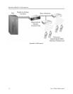
25-Pair Cables RJ-21 male at MCU end, required to connect the
shelves to the cross-connect blocks.
Cross-Connect Blocks Required to connect the PBX ports and the
Base Stations to the MCU.
Quick Clip Fuse Required with an RCO400 Outdoor Base Station
or when a Base Station is located in a separate building from the
SpectraLink 6300 MCU. Recommended Quick Clip Fuse is
available from Reliable Electric, Model # RSCP-2.
Ladder Polycom installation crew will require a ladder to reach
the Base Station locations. Ensure that a ladder of adequate height
is available for the crew’s exclusive use upon arrival.