


PN: 1725-36122-001_M.doc
19
Site Preparation
The following steps must be completed before installing the system
hardware. If the steps are not already completed refer to each
individual section for details.
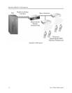
MCU location prepared. Typically the MCU is installed in the
telephone equipment room. This location must have sufficient
backboard space or rack space, and -48 volt power available.
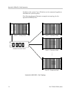
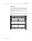
The correct number of cross-connect blocks (or equivalent) are
installed and connected to a 25-pair Telco wire terminated with an
RJ-21 male connector at the MCU location. The number of blocks
required depends on the number and type of Interface Modules
installed. Refer to Chapter 4, section
Prepare Demarc Blocks
for
more information.
A two-pair cable to each Base Station as designated on the
building floor plans.
The Base Station wiring is terminated with RJ-45 crimp-on plugs
at the designated Base Station locations. Refer to Chapter 4,
section
Terminate Cables at Base Station Locations
for more
information.
The Base Station wire is terminated at the appropriate cross-
connect demarc blocks. Refer to Chapter 4, section
Connect Cables
from Base Stations and Phone Lines to Demarc Blocks
.
The analog or digital phone extensions from the phone system are
terminated at the appropriate cross-connect demarc block and the
block is labeled. Refer to Chapter 4, section
Connect Cables from
Base Stations and Phone Lines to Demarc Blocks
.
A dedicated dial line is available with an RJ-11 jack for the
diagnostic modem.
An IBM-compatible PC is available to serve as the Operator’s
Console for system administration.
A system administrator is designated for the SpectraLink system.
This person should be present for the installation. The Polycom
field service engineer will provide system training to the system
administrator on the day following the installation.
4