


2
• 1145B1 Bulk Power Supply (PEC: 2404-010)
Battery for the 1145B1 (2 amp battery = PEC: 24700;
or 5 amp battery = PEC: 24701)
• KS-22911 L2 (replaced by the MSP-1 Power Supply and 1151A1/A2 Power
Supplies) — This power supply cannot be used with the 8411.
NOTES: The MSP-1, the 1151A1 and A2, and the 1145B are global power supplies.
It is recommended that the 1145A and the 1145B Bulk Power Supplies be used as
auxiliary power for the 8434DX voice terminal. These power supplies provide battery
back-up, and therefore when power outages occur, the 8434DX display will continue
to operate.
If an 8434DX voice terminal with attached adjunct equipment is connected to an
expansion module, it should be locally powered by an MSP-1 or an 1151A1 or A2. If
this configuration is closet powered by an 1145A, two ports must be used. A KS-
22911 L2 cannot be used in this situation.
General Notes for Installation
Regardless of which configuration is in use, ALL wiring between the PBX and the
terminal MUST consist of twisted-pairs, including the modular line cord. The line
cord must be a D8W, which consists of four twisted-pairs, or a Lucent Technologies
approved equivalent.
Twisted-pair wiring is used to make lines less sensitive to crosstalk. Therefore, failure
to use twisted pair wiring may result in less-than-optimum performance of the
terminal and may also contribute to problems with the line.
An 8-wire modular cord MUST be used for all 4-wire and any 2-wire installations
requiring auxiliary power.
You do NOT need to change any settings on the voice terminal for 2-wire or 4-wire
installations. The voice terminal is able to detect whether it is in a
2-wire or a 4-wire configuration.
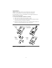
Desktop Installation
The following instructions are for a desktop installation. If you are mounting the
voice terminal on the wall, proceed to the next section, “Wall Installation.”
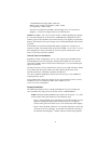
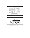
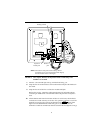
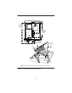
NOTE: During the desktop installation procedure, refer to Figures 1, 2, 3, and 4
for the location of the jacks referred to in the following steps.
• Figure 1 shows the back of one of the 8403 voice terminal models. (Use this
figure for installing the 8403, 8405, and 8410. However, note that the
location of the jacks on the back of your voice terminal may differ slightly.)
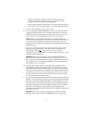
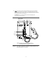
• Figure 2 shows the back of the 8411 voice terminal, and Figure 3 shows the
two jacks on the rear of the 8411. Use the RS-232-D jack for connecting a
PC dedicated to PassageWay
®
Solution software and the Analog Adjunct