


3
jack for connecting an analog device such as a modem, answering
machines, fax machines, audio teleconferencing equipment, or TTY
machines commonly used by the hearing impaired.
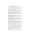
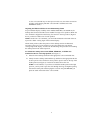
• Figure 4 shows the back of the 8434DX voice terminal. (Note that the jacks
on the back of your voice terminal may be in a slightly different location.)
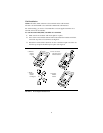
1. Turn the voice terminal face down on a flat surface.
2. If you are installing an 8405D, 8405D Plus, or 8410D voice terminal, refer to
“Adjusting the 8405 and 8410 Voice Terminal Desktop Stand” for choosing
whether the desktop stand should be in the high or low position. On the 8411,
decide whether you want the kickstand in the up or the down position.
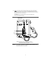
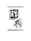
NOTE: Figure 1 shows the back of the 8403 voice terminal, although the
location of the routing channels on some 8403 voice terminals and on the 8405
and 8410 may differ slightly from the 8403 shown in the figure. Also, the
Handset jack on some 8403 voice terminals and on the 8405 and 8410 may be in
a different location.
3. Snap one end of the line cord into the “LINE” jack and the adjunct cord (if
applicable) into the Adjunct jack on the back of the voice terminal. (The
Adjunct jack is labeled , except on the 8411, where it is labeled
“ADJUNCT.”) For more information on installing adjuncts, refer to the section
“Attaching Adjunct Equipment.”
IMPORTANT: If you are routing the cords on the 8405D, 8405D Plus, or
8410D voice terminal and the desktop stand is in the high position, you may
need to place the cords through the long, rectangular opening that surrounds the
jacks and plug the cords into the jacks BEFORE you insert the desktop stand
onto the back of the voice terminal.
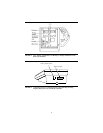
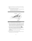
4. Thread the line cord (and adjunct cord, if applicable) through the routing
channel leading to the top of the desktop stand, as shown in Figure 1 (on the
8403, 8405, and 8410 voice terminals), Figure 2 (on the 8411 voice terminal)
and Figure 4 (on the 8434DX voice terminal). Note, however, that the location
of the routing channels on some voice terminals may differ from those on the
voice terminals in these figures. Make sure that each cord is placed securely
under the square tabs in the routing channel.
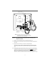
5. If you are using an 8434DX with an attached 801A Expansion Module, plug the
D6AP-87 cord, shipped with the expansion module, into the Expansion Module
jack on the voice terminal (labeled “EX MOD”) and then plug the free end of
the cord into the jack on the expansion module. The cord should be threaded
through the routing channels on the 8434DX. See Figure 4. For more detailed
instructions on installing the expansion module to the 8434DX, use the
instructions titled “801A Expansion Module Instruction Manual,” shipped with
the expansion module.
IMPORTANT: An 801A Expansion Module can be used ONLY with an
8434DX voice terminal connected to a DEFINITY G3V3.3 or later switch.