


7
2
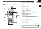
PANEL DESCRIPTION
2
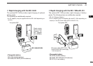
❍ While in the digital (DV) mode operation with an optional
UT-118
DIGITAL UNIT
installed.
➥ “” appears while the digital code (CSQL) squelch
function is in use. (p. 49)
➥ “” appears while the call sign (DSQL) squelch func-
tion is in use. (p. 49)
➥ “” appears with the “ ” or “ ” indicator while the
pocket beep function (CSQL or DSQL) is in use.
(p. 48)
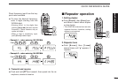
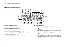
y TRANSMIT INDICATOR (p. 15)
Appears during transmit.
u FREQUENCY READOUT
Shows operating frequency, channel number or channel
names, depending on display type (p. 16).
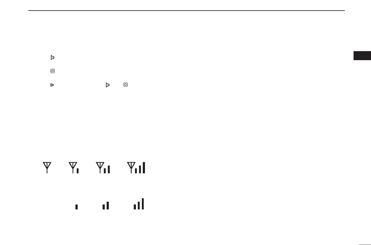
i SIGNAL INDICATOR
➥ Shows receiving signal strength as below.
➥ Shows the output power level while transmitting.
o BUSY INDICATOR
➥ Appears when a signal is being received or the squelch
is open.
➥ Blinks while the monitor function is activated. (pgs. 15, 49)
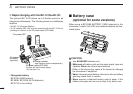
!0 PAGER CALL INDICATOR (p. 41)
Blinks when a pager call is received. (This indicator ap-
pears only when an optional UT-108
DTMF DECODER UNIT
is installed.)
!1 DIGITAL MODE INDICATOR (p. 45)
Appears when digital mode is selected. (This indicator ap-
pears only when an optional UT-118
DIGITAL UNIT
is in-
stalled.)
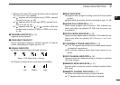
!2 LOW/MIDDLE POWER INDICATOR (p. 15)
➥ “L” or “M” appears when the low or middle output power
is selected, respectively.
➥ No indicator appears when high output power is se-
lected.
!3 SKIP CHANNEL INDICATOR (p. 32)
Appears when the selected memory channel is specified
as a skip channel.
!4 MEMORY MODE INDICATOR (p. 21)
Appears while in memory mode or channel number indica-
tion mode.
!5 MEMORY CHANNEL INDICATOR (p. 21)
➥ Shows the selected memory channel number.
➥ “C” appears when the call channel is selected.
Low Middle High
Weak ⇐ RX Signal level ⇒ Strong