


SECTION 3 DISASSEMBLY AND OPTION INSTRUCTIONS
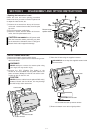
• Opening the transceiver’s case
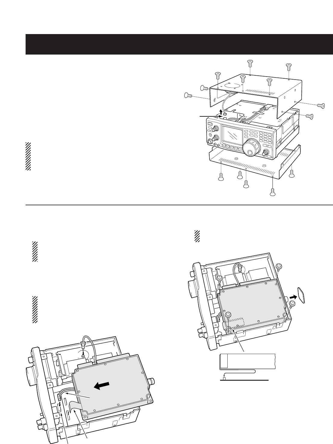
Follow the case and cover opening procedures
shown here when you want to install an optional unit
or adjust the internal units, etc.
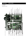
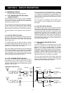
q Remove the 5 screws from the top of the trans-
ceiver and 4 screws from the sides, then lift up the
top cover.
w Turn the transceiver upside down.
e Remove 5 screws from the bottom of the trans-
ceiver, then lift up the bottom cover.
CAUTION: DISCONNECT the DC power cable
from the transceiver before performing any work
on the transceiver. Otherwise, there is a danger of
electric shock and/or equipment damage.
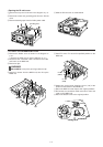
• UX-910 1200MHz BAND UNIT
q Remove the bottom cover as shown above.
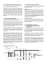
w Remove the antenna plate from the chassis using a stan-
dard screw driver.
WARNING!
NEVER attempt to remove the antenna plate using
your finger, this may result in injury.
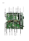
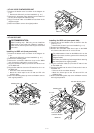
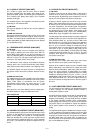
e Connect the FFC (Flexible Flat Cable) of the
UX-910 to J2 on the MAIN unit, DC power cable to the
power connector (W305) from the PA unit and the coaxi-
al cable to J541 on the PLL unit.
CAUTION
NEVER catch the cables from the optional DSP unit(s)
between chassis and the UX-910, this may damage
the DSP unit(s) and/or transceiver.
J541
J2
UX-910
PLL unit
Power connector
DC power cable
Coaxial cable
Flexible flat cable
Disconnect the
speaker cable.
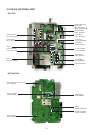
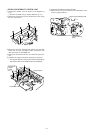
r Place the UX-910 using the supplied 4 screws.
BE CAREFUL not to drop the supplied screws inside
the transceiver.
Antenna plate
UX-910
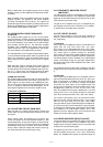
Turn the flexible flat cable up under the UX-910.
J2
MAIN unit
Flexible flat cable
UX-910
t Return the bottom cover to its original position.
3 - 1