


*This output level of a standard signal generator (SSG) is indicated as SSG’s open circuit.
5 - 18
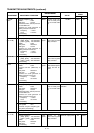
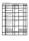
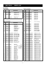
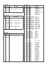
5-7 UX-910 ADJUSTMENTS
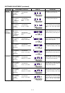
2ND LO LOCK
VOLTAGE
1ST LO LOCK
VOLTAGE
RECEIVER
GAIN
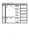
ATT GAIN
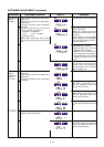
IDLING
POWER
BALLANCE
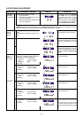
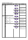
TRANSMITTER
GAIN
ADJUSTMENT
ADJUSTMENT ADJUSTMENT CONDITION
MEASUREMENT
VALUE
POINT
UNIT LOCATION UNIT ADJUST
1
1
2
1
1
1
1
2
3
4
1
• Connect an optional UX-910 (1200
MHz band unit).
• Display frequency: 1270.5000 MHz
• Receiving
• Display frequency: 1240.0000 MHz
• Receiving
• Display frequency: 1300.0000 MHz
• Receiving
• Display frequency: 1280.0000 MHz
• Connect a standard signal generator
to [12 ANT] connector and set as:
Frequency : 1280.0000 MHz
Level : 710 µV* (–50 dBm)
Modulation: OFF
• Receiving
• Display frequency: 1280.0000 MHz
• [ATT] : ON
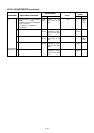
• Set an SSG as :
Frequency : 1280.0000 MHz
Level : 710 µV* (–50 dBm)
Modulation: OFF
• Receiving
• Display frequency: Any
• Mode : CW
• Preset R61, R67, R83 to max.
clockwise, R13 to max. counter
clockwise, and C332 to center.
• Connect an RF power meter to [12
ANT].
• Connect an SSG to the check point
CP311 and set as :
Frequency : 10.8500 MHz
Level : OFF
• Transmitting
• Display frequency: Any
• Mode : CW
• Connect an SSG to the check point
CP311 and set as :
Frequency : 10.8500 MHz
• Transmitting
• Display frequency: 1240.0000 MHz
• Transmitting
• Display frequency: 1300.0000 MHz
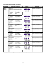
• Transmitting
• Display frequency: 1270.0000 MHz
• Set an SSG as :
Frequency : 10.8500 MHz
Level : 18 mV* (–22 dBm)
• Transmitting
MAIN
(UX-910)
MAIN
(UX-910)
MAIN
(UX-910)
MAIN
(UX-910)
MAIN
(UX-910)
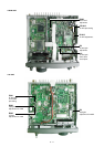
Rear
panel
Rear
panel
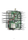
Connect a digital
multimeter or oscillo-
scope to check point
CP701.
Connect a digital
multimeter or oscillo-
scope to check point
CP501.
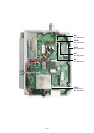
Connect a spectram
analyzer to check
point CP311.
Connect a spectram
analyzer to check
point CP311.
Connect a digital
multimeter between
check points CP321
and CP322.
Connect an RF
power meter to [12
ANT].
Connect an RF
power meter to [12
ANT].
2.6–3.8 V
6.0–7.0 V
3.4–4.4 V
–34 dBm (16 dB gain)
–14 dBm (20 dB of gain
difference between the
attenuator ON and
OFF.)
0.5 V
voltage difference
5 W
Read the RF power
meter indication.
Same power as step 2
5 W
MAIN
(UX-910)
MAIN
(UX-910)
MAIN
(UX-910)
MAIN
(UX-910)
MAIN
(UX-910)
Verify
Verify
R224
R288
R13
Adjust
SSG’s
level
Verify
C332
R83
Repeat step 2 and step 3 several times until power difference is minimum.