


4 - 3
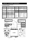
4-1-11 NOISE BLANKER CIRCUIT (MAIN UNIT)
The noise blanker circuit detects pulse-type noises, and
stops IF amplifier operation during detection.
A portion of the 10 MHz IF signal from the bandpass filter
(FI51 [Main], FI651 [Sub]) is amplified at the noise amplifier
circuit (Q102, IC101, Q101 [Main], Q702, IC701, Q701
[Sub]). The amplified signal is rectified at the noise detector
(D371 [Main], D701 [Sub]) for conversion into DC voltage.
The DC voltage is amplified at the DC amplifier circuit (Q105
[Main], Q705 [Sub]) and then applied to the noise blanker
control circuit (Q52, Q107 [Main], Q652, Q707 [Sub]) to stop
amplification of the IF amplifier circuit (Q51 [Main], Q651
[Sub]).
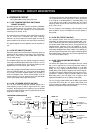
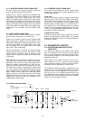
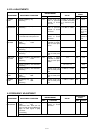
4-1-12 AGC CIRCUIT (MAIN UNIT)
The AGC (Auto Gain Control) circuit reduces IF amplifier
gain to keep the audio output at a constant level.
A portion of the 10 MHz IF signal from the IF amplifier (Q352
[Main], Q852 [Sub]) is applied to the AGC detector circuit
D303 [Main], D902 [Sub]). The detected signal is then ampli-
fied at the DC amplifier circuit (Q305 [Main], Q901 [Sub])
and then applied to the IF amplifiers (Q51, Q351, Q352
[Main], Q651, Q851, Q852 [Sub]).
When strong signals are received, the detected voltage
increases and the output level of the DC amplifier, as AGC
voltage, decreases. The AGC voltage is used for the bias
voltage for the IF amplifiers, therefore, the IF amplifier gain
is decreased.
AGC response time is controlled by changing the time con-
stant at the AGC control line with a resistor and capacitor.
While AGC is set to slow, the resistor (R312 [Main], R914
[Sub]) and capacitor (C306 [Main], C911 [Sub]) are con-
nected to the AGC control line. While AGC is set to fast,
R311 [Main], R913 [Sub] are connected to the AGC control
line. Due to Q304 and Q303 [Main]/Q905 and Q904 [Sub]
being switched ON that controlled by the “AGSM”, “AGFM”
[Main], “AGSS”, “AGFS” [Sub]. Also, R310 [Main]/R912
[Sub] is connected to the AGC control line due to Q302
[Main]/Q903 being switched ON while scanning for faster
response than AGC fast mode that controlled by the
“AGRM” [Main], “AGRS” [Sub].
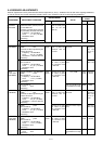
4-1-13 S-METER CIRCUIT (MAIN UNIT)
The S-meter circuit indicates the relative received signal
strength while receiving and changes depending on the
received signal strength.
(1) FM mode
Some of the amplified IF signal is applied to the S-meter
detector section in the FM IF IC (IC401 [Main], IC951 [Sub])
to be converted into DC voltage. The converted signal is out-
put from pin 12 and applied to the meter amplifier circuit
(IC1804c [Main], IC1804a [Sub]). The amplified signal is
then applied to the CPU (DISPLAY board; IC1) passing
through the analog multiplexer (DISPLAY board; IC4, pins
12 and 1) via the “SMLM [Main]/SMLS [Sub]” line. The CPU
then outputs S-meter control signal.
(2) SSB and CW modes
A portion of the AGC control signal is applied to the meter
amplifier (IC1804d [Main], IC1804b [Sub]). The amplified
signal is then applied to the CPU via the analog multiplexer
to control the S-meter.
4-2 TRANSMITTER CIRCUITS
4-2-1 MICROPHONE AMPLIFIER CIRCUIT
(MAIN UNIT)
The microphone amplifier circuit amplifies audio signals
from the microphone or ACC connector and then applies
them to the FM modulation or balanced modulator circuit.
One microphone amplifier circuit is commonly used for both
FM/SSB and VHF/UHF.
Audio signals from the [MIC] connector enter the micro-
phone amplifier IC (IC1701, pin 22) and are then amplified
at the microphone amplifier or speech compressor section.
Compression level is adjusted by the setting mode.
The amplified or compressed signals are applied to the VCA
section of IC1701. The microphone gain setting from the D/A
converter (IC1521, pin 8) is applied to the VCA control ter-
minal (IC1701, pin 10). The resulting signals from pin 9 are
then applied to the buffer-amplifier (Q1651) via the analog
switch (IC1653a). External modulation input from the [ACC]
socket (pin 4) is also applied to Q1651.
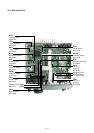
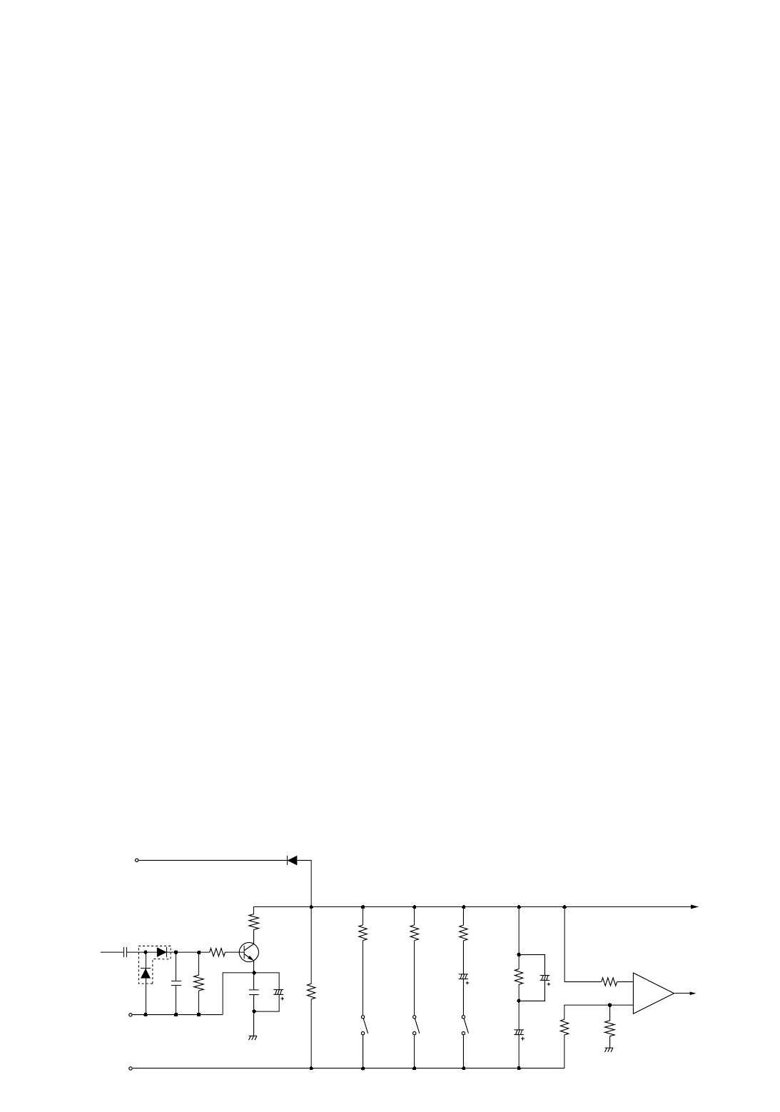
• AGC CIRCUIT FOR MAIN BAND
AGC line
RFGM
(RF/SQL control)
SLOW
Q306
9 V
–5 V
D303
C309
2nd IF
signal
C306 R312Q304
FAST
C307
R313
C308
R310Q302
C311
C310
C312
R303
R317
R304
R311Q303
D302
R316
R314
R302
Meter
amp.
IC1804d
“SMLM”
AGC det.
S-meter signal
+
–
12
14
13
SCAN
R315