


*This output level of a standard signal generator (SSG) is indicated as SSG’s open circuit.
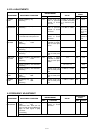
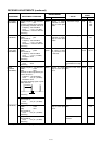
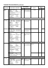
RECEIVER ADJUSTMENTS (continued)
430 M PEAK
(MAIN BAND)
430 M PEAK
(SUB BAND)
430 M
TOTAL GAIN
(MAIN BAND)
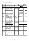
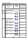
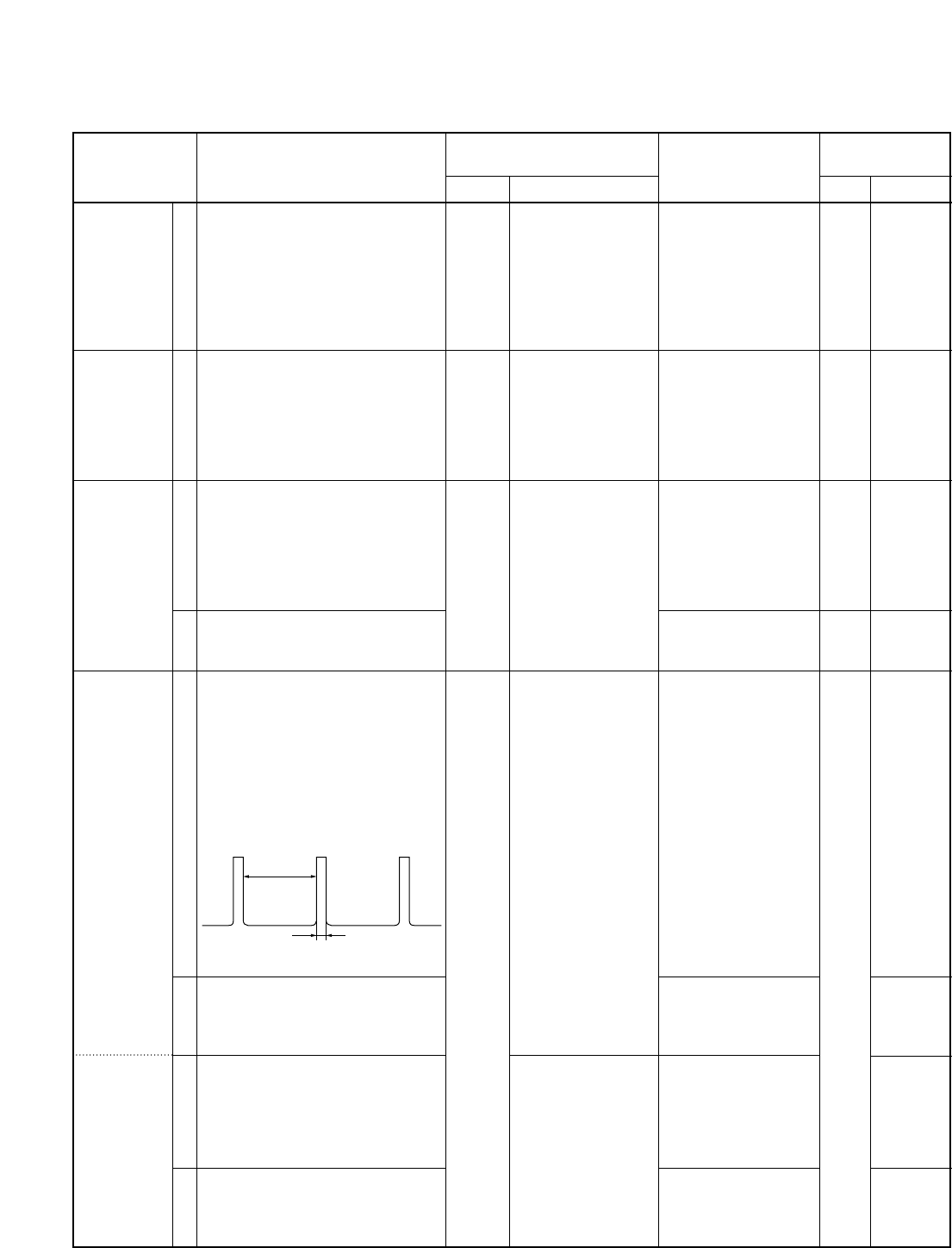
NOISE
BLANKER
(MAIN BAND)
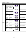
(SUB BAND)
1
1
1
2
1
2
3
4
• Display frequency: 435.0200 MHz
• Mode : FM
• Connect a standard signal generator
to [UHF ANT] connector and set as:
Frequency : 435.0200 MHz
Level : 1 µV* (–107 dBm)
Modulation:
1 kHz/±5.0 kHz Dev.
• Receiving
• Sub display freq. : 435.0200 MHz
• Mode : FM
• Set an SSG as :
Frequency : 435.0200 MHz
Level : 1 µV* (–107 dBm)
Modulation:
1 kHz/±5.0 kHz Dev.
• Receiving
• Display frequency: 435.0200 MHz
• Mode : USB
• Set an SSG as :
Frequency : 435.0215 MHz
Level : 1 mV* (–47 dBm)
Modulation:
OFF
• Receiving
• Set an SSG as :
Level : OFF
• Receiving
• Display frequency: 145.9800 MHz
• Mode : USB
• [NB] : OFF
• Connect an SSG to [VHF ANT] con-
nector and set as :
Frequency : 145.98150 MHz
Level : 5.6 µV* (–92 dBm)
Modulation: OFF
and apply following signal to [VHF
ANT] connector.
• Receiving
• [NB] : ON
• Set an SSG as :
Level : 3.2 µV* (–97 dBm)
•
Receiving
• Sub display freq. : 145.9800 MHz
• Mode : USB
• [NB] : OFF
• Set an SSG as :
Level : 5.6 µV* (–92 dBm)
•
Receiving
• [NB] : ON
• Set an SSG as :
Level : 3.2 µV* (–97 dBm)
•
Receiving
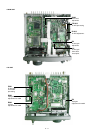
MAIN
MAIN
Rear
panel
MAIN
100 msec.
1 msec.
5 - 6
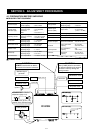
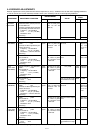
ADJUSTMENT
ADJUSTMENT ADJUSTMENT CONDITION
MEASUREMENT
VALUE
POINT
UNIT LOCATION UNIT ADJUST
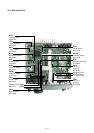
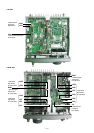
Connect a digital
multimeter or oscillo-
scope to check point
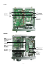
CP851.
Connect a digital
multimeter or oscillo-
scope to check point
CP852.
Connect an AC milli-
volt meter to [EXT
SP] connector with
an 8 Ω load.
Connect an oscillo-
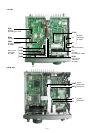
scope to check point
CP101.
Connect an oscillo-
scope to check point
CP701.
Maximum voltage
Maximum voltage
1.0 V (0 dB)
100 mV (20 dB of AF
level difference as step
1.)
Maximum noise wave-
form
The noise must be
blanked.
Maximum noise wave-
form
The noise must be
blanked.
PA
PA
Front
panel
PA
MAIN
L22,
L23,
L282,
L283
L280,
L281
main [AF]
volume
R61
L102,
L103
Verify
L703,
L704
Verify