


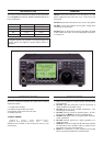
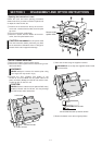
INTRODUCTION
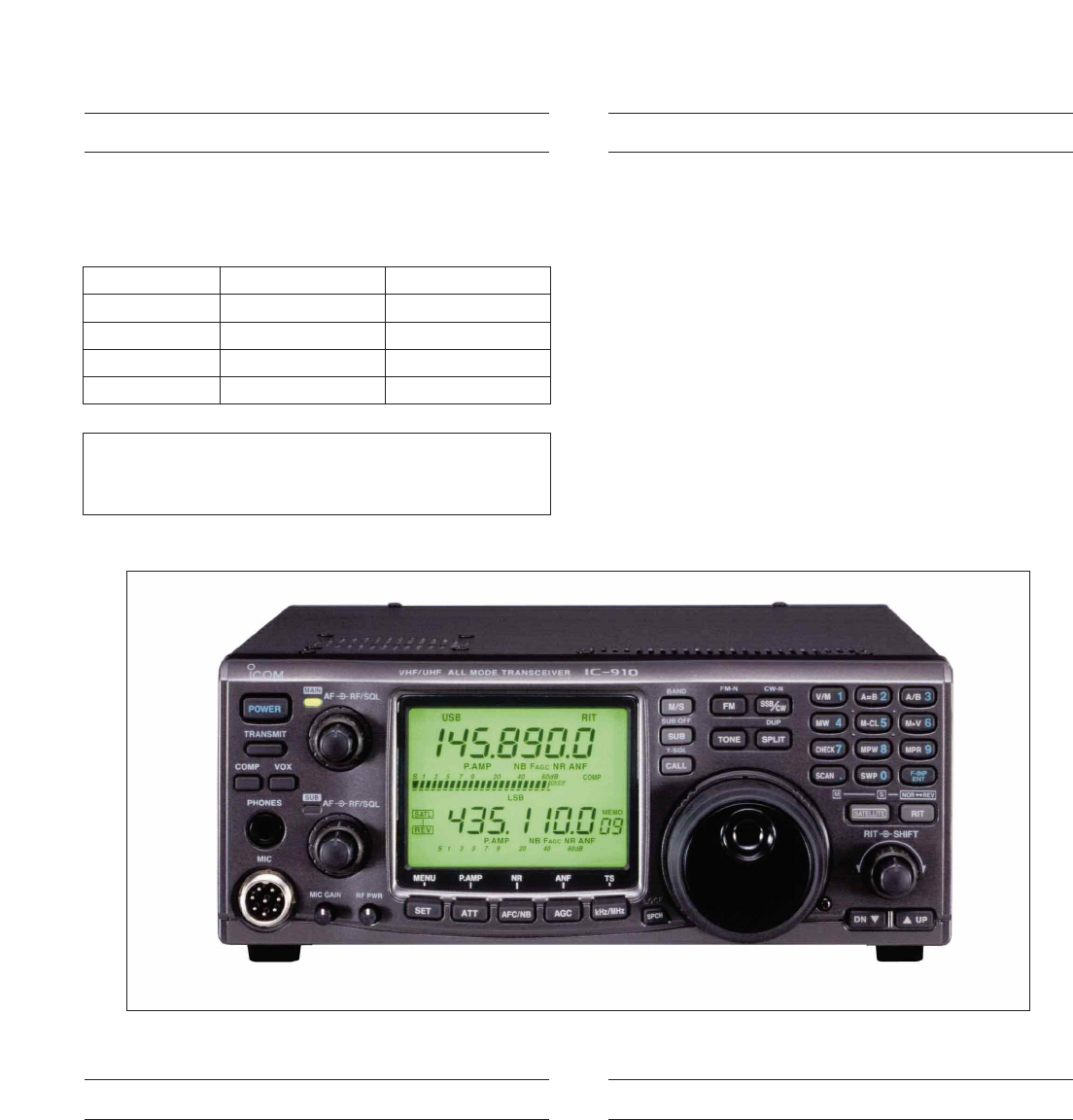
This service manual describes the latest service information
for the IC-910H VHF/UHF ALL MODE TRANSCEIVER at the
time of publication.
VERSION No.
#02
#04
#06
#07
VERSION
Europe
Australia
U.S.A.
Korea
SYMBOL
EUR
AUS
USA-1
KOR
To upgrade quality, any electrical or mechanical parts and
internal circuits are subject to change without notice or
obligation.
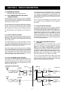
DANGER
NEVER connect the transceiver to an AC outlet or to a DC
power supply that uses more than 16 V. This will ruin the
transceiver.
DO NOT expose the transceiver to rain, snow or any liquids.
DO NOT reverse the polarities of the power supply when
connecting the transceiver.
DO NOT apply an RF signal of more than 20 dBm (100 mW)
to the antenna connector. This could damage the transceiv-
er’s front end.
ORDERING PARTS
Be sure to include the following four points when ordering
replacement parts:
1. 10-digit order numbers
2. Component part number and name
3. Equipment model name and unit name
4. Quantity required
<SAMPLE ORDER>
1110003140 IC LA1150N IC-910H MAIN UNIT 5 pieces
8810005770 Screw BiH M3×8 ZK IC-910H Cover 10 pieces
Addresses are provided on the inside back cover for your
convenience.
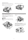
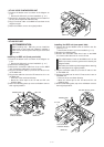
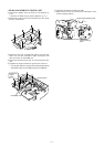
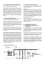
REPAIR NOTES
1. Make sure a problem is internal before disassembling
the transceiver.
2. DO NOT open the transceiver until the transceiver is
disconnected from its power source.
3. DO NOT force any of the variable components. Turn
them slowly and smoothly.
4. DO NOT short any circuits or electronic parts. An insu-
lated tuning tool MUST be used for all adjustments.
5. DO NOT keep power ON for a long time when the trans-
ceiver is defective.
6. DO NOT transmit power into a signal generator or a
sweep generator.
7. ALWAYS connect a 50 dB to 60 dB attenuator between
the transceiver and a deviation meter or spectrum ana-
lyzer when using such test equipment.
8. READ the instructions of test equipment thoroughly
before connecting equipment to the transceiver.