


5 - 2
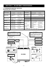
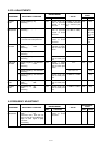
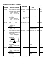
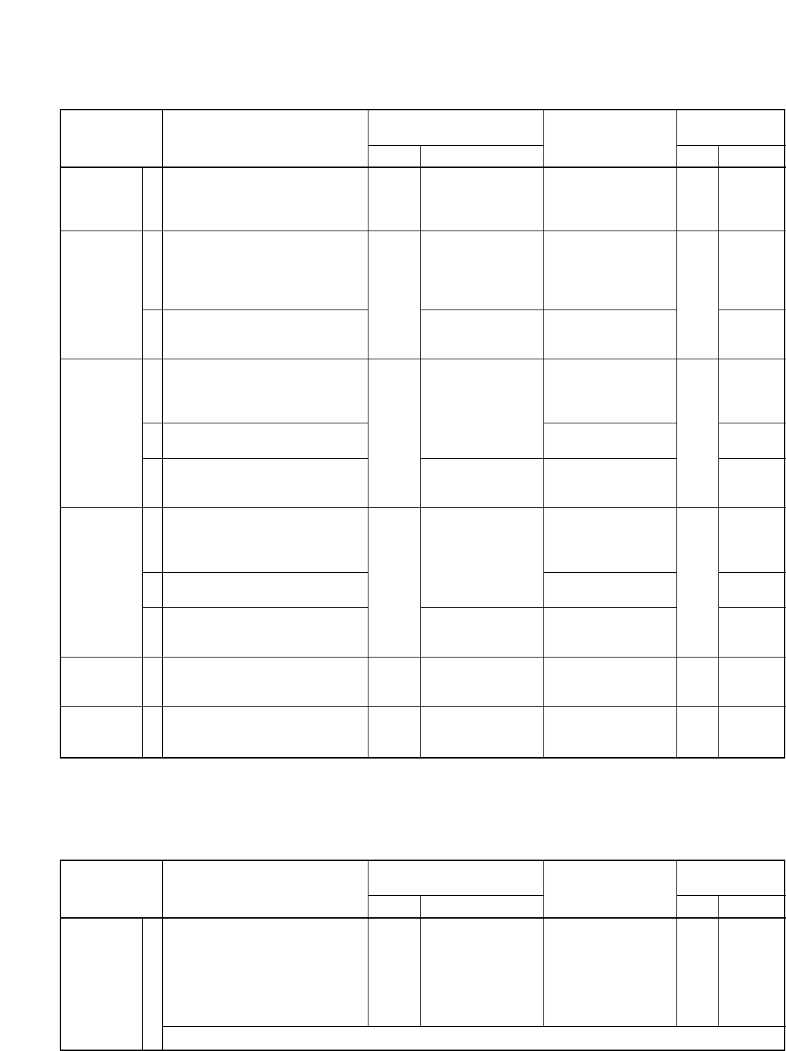
5-2 PLL ADJUSTMENTS
30.2 MHz
LEVEL
REFERENCE
FREQUENCY
144M LOCK
VOLTAGE
440M LOCK
VOLTAGE
MAIN BFO
LEVEL
SUB BFO
LEVEL
ADJUSTMENT
ADJUSTMENT ADJUSTMENT CONDITION
MEASUREMENT
VALUE
POINT
UNIT LOCATION UNIT ADJUST
1
1
2
1
2
3
1
2
3
1
2
• Display frequency: Any
• Receiving
• Display frequency: Any
• Receiving
This adjustment must be performed
at 5 minutes later after power ON.
• Display frequency: 173.9800 MHz
• Mode : USB
• Receiving
• Display frequency: 136.0200 MHz
• Receiving
• Display frequency: 155.0000 MHz
• Receiving
• Display frequency: 479.9800 MHz
• Mode : USB
• Receiving
• Display frequency: 420.0200 MHz
• Receiving
• Display frequency: 450.0000 MHz
• Receiving
• Display frequency: Any
• Mode :USB
• Receiving
• Sub display freq. : Any
• Mode :USB
• Receiving
PLL
PLL
PLL
PLL
PLL
PLL
Connect an RF volt-
meter or spectram
analyzer to check
point J541.
Connect an RF volt-
meter or spectram
analyzer to check
point P551.
Connect a frequency
counter to check
point P551.
Connect a digital
multimeter or oscillo-
scope to check point
CP100.
Connect an RF volt-
meter to check point
P251.
Connect a digital
multimeter or oscillo-
scope to check point
CP300.
Connect an RF volt-
meter to check point
P421.
Connect an RF volt-
meter to check point
P601.
Connect an RF volt-
meter to check point
P701.
–10 dBm (or more than
–11.5 dBm, when R570
is in maximum posi-
tion.)
Maximum level
(–13 dBm to –7dBm)
60.400000 MHz
2.7 V
0.6 V to 1.6 V
–10 dBm to –4 dBm
3.4 V
0.5 V to 1.5 V
–16 dBm to –10 dBm
–11 dBm to –5 dBm
–11 dBm to –5 dBm
PLL
PLL
PLL
PLL
PLL
PLL
R570
Adjust in
sequence
L551, L552
several
times.
The trimmer
capacitor of
X512.
L193
Verify
Verify
C402
Verify
Verify
Verify
Verify
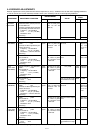
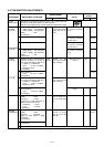
5-3 FREQUENCY ADJUSTMENT
FM TX-LO
FREQUENCY
ADJUSTMENT
ADJUSTMENT ADJUSTMENT CONDITION
MEASUREMENT
VALUE
POINT
UNIT LOCATION UNIT ADJUST
1 • Display frequency: Any
• Mode : FM
• Disconnect P501, P502 (PA unit)
from J51 and J52 on the MAIN unit.
• Apply no audio signals to [MIC]
connector.
• Transmitting
MAIN Connect a frequency
counter to check
point CP51.
10.85000 MHz MAIN L255
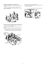
After adjustment, connect P501, P502 (PA unit) to J51, J52 on the MAIN.