


HUAWEI MC509 CDMA LGA Module
Hardware Guide
Description of the Application Interfaces
Issue 01 (2011-04-08)
Huawei Proprietary and Confidential
Copyright © Huawei Technologies Co., Ltd.
39
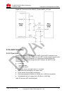
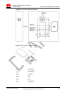
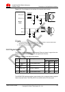
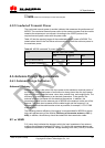
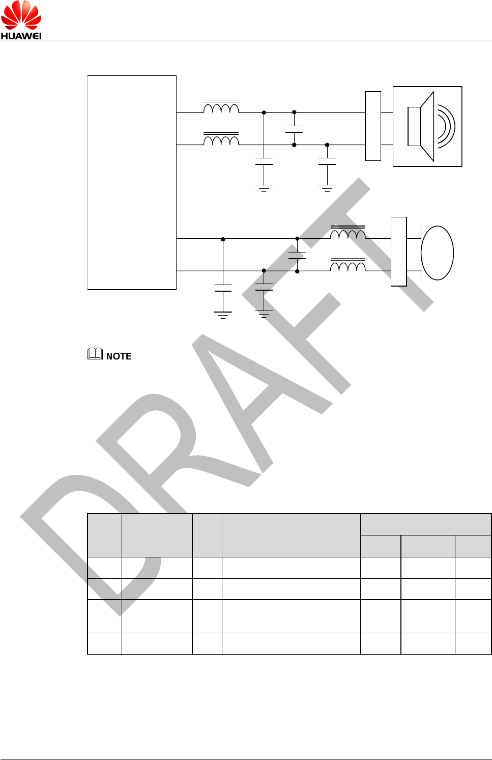
Figure 3-13 Circuit diagram of the interface of the second audio channel
Module
(DCE)
+
_
ESD protection
ESD protection
ferrite bead
SPKR_OUT_P
SPKR_OUT_N
MIC2_P
MIC2_N
ferrite bead
ferrite bead
ferrite bead
1nF
1nF 1nF
1nF
1nF1nF
Speaker
MIC
+
_
It is recommended that a TVS be used on the related interface, to prevent electrostatic
discharge and protect integrated circuit (IC) components.
Data only does not support the voice function.
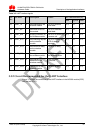
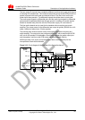
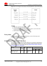
3.8.2 Digital Audio
The MC509 provides one digital audio channels (Data only doesn’t support the voice
function). Table 3-12 lists the signals on the digital audio interface.
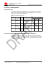
Table 3-12 Signals on the digital audio interface
Pin
No.
Pin Name
I/O
Description
DC Characteristics (V)
Min
Typical
Max
5
PCM_SYNC
O
PCM interface sync
-0.3
2.6
2.9
6
PCM_DIN
I
PCM I/F data in
-0.3
2.6
2.9
7
PCM_DOU
T
O
PCM I/F data out
-0.3
2.6
2.9
8
PCM_CLK
O
PCM interface clock
-0.3
2.6
2.9
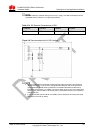
The MC509 PCM interface enables communication with an external codec to support
linear and μ-law format. The PCM_SYNC runs at 8kHz with a 50% duty cycle.