


HUAWEI MC509 CDMA LGA Module
Hardware Guide
Description of the Application Interfaces
Issue 01 (2011-04-08)
Huawei Proprietary and Confidential
Copyright © Huawei Technologies Co., Ltd.
37
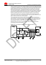
To meet the requirements of ETSI TS 102 230protocols and electromagnetic
compatibility (EMC) authentication, the UIM card socket should be placed near the
LGA interface (it is recommended that the PCB circuit connecting the LGA
interface and the UIM card socket not exceed 100mm), because a long circuit
may lead to wave distortion, thus affecting signal quality.
It is recommended that the user should wrap the area adjacent to the UIM_CLK
and UIM_DATA signal wires with a ground wire. The GND pin of the UIM card
socket and the GND pin of the UIM card must be well connected to the power
GND pin supplying power to the MC509 module.
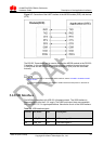
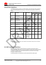
A 0.1μF capacitor is placed between the UIM_VCC and GND pins in a parallel
manner. Three 10pF or 33pF capacitors are placed between the UIM_DATA and
GND pins, the UIM_RST and GND pins, and the UIM_CLK and GND pins in
parallel to filter interference from RF signals.
It is not recommended that pull the UIM_DATA pin up during design as a 15000-
ohm resistor is used to connect the UIM_DATA pin to the UIM_VCC.
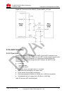
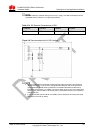
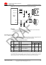
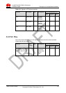
3.7.3 ESD Protection for the UIM Card Interface
It is recommended to take electrostatic discharge (ESD) protection measures near
the UIM card socket. Figure 3-11 shows ESD protection circuit of the UIM card, in
which the transient voltage suppressor (TVS) diode is placed as close as possible to
the UIM card socket, and the GND pin of the ESD protection component is well
connected to the power GND pin that supplies power to the MC509 module.
Figure 3-11 ESD protection circuit on the UIM card
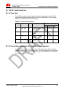
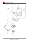
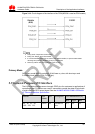
3.8 Audio Interface
3.8.1 Analogue Audio
The MC509 provides two audio I/O channels (Data only doesn’t support the voice
function).