


HUAWEI MC509 CDMA LGA Module
Hardware Guide
Description of the Application Interfaces
Issue 01 (2011-04-08)
Huawei Proprietary and Confidential
Copyright © Huawei Technologies Co., Ltd.
27
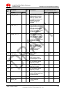
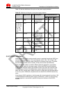
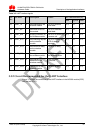
It is recommended that use resistance of 0ohm in the DTE to isolate signals transmitted from
above pins in Table 3-5
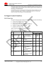
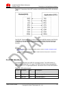
3.4.2 Input Signal Control Pins
The MC509 module implements power-on and power-off and resets the hardware
through the input signal control pins.
The power-on, power-off, and reset control parts of the interface of the MC509
module include power-on/power-off interface signal (POWER_ON_OFF) and the
hardware reset interface signal (RESIN_N).
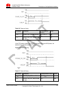
The POWER_ON_OFF pin is used to implement power-on and power-off. If the
POWER_ON_OFF pin is pulled down for at least 0.5s, the module is powered on; if
the POWER_ON_OFF pin is pulled down for at least 2.5s again, the module is
powered off.
The RESET pin is used to reset the hardware. When the software stops responding,
the RESET pin can be pulled down for 100ms to reset the hardware.
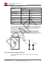
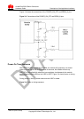
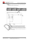
As the RESET and POWER_ON_OFF signals are relatively sensitive, it is
recommended that you install a 10nF capacitor near the RESET and
POWER_ON_OFF pins of the interface for filtering. In addition, when you design a
circuit on the PCB of the interface board, it is recommended that the circuit length not
exceed 20mm and that the circuit be kept at a distance of 2.54mm (100mil) at least
from the PCB edge. Furthermore, you need to wrap the area adjacent to the signal
wire with a ground wire. Otherwise, the module may be reset due to interference.