


HUAWEI MC509 CDMA LGA Module
Hardware Guide
Description of the Application Interfaces
Issue 01 (2011-04-08)
Huawei Proprietary and Confidential
Copyright © Huawei Technologies Co., Ltd.
21
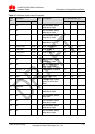
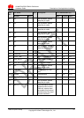
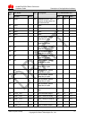
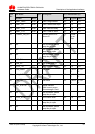
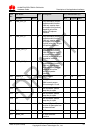
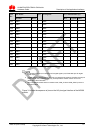
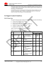
PIN
No.
Pin Name
I/O
Description
DC Characteristics (V)
Normal
MUX
Min
Typical
Max
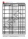
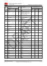
132
GND
-
-
GND
-
-
-
133
GND
-
-
GND
-
-
-
134
GND
-
-
GND
-
-
-
135
GND
-
-
GND
-
-
-
136
GND
-
-
GND
-
-
-
137
GND
-
-
GND
-
-
-
138
GND
-
-
GND
-
-
-
139
GND
-
-
GND
-
-
-
140
GND
-
-
GND
-
-
-
141
GND
-
-
GND
-
-
-
142
GND
-
-
GND
-
-
-
143
GND
-
-
GND
-
-
-
144
GND
-
-
GND
-
-
-
145
GND
-
-
GND
-
-
-
P indicates power pins; I indicates pins for digital signal input; O indicates pins for digital
signal output.
The NC (Not Connected) pins are internally connected to the module. Therefore, these pins
should not be used, otherwise they may cause problems. Please contact us for more
details about this information.
When the MC509 module works on master mode, PCM_CLK and PCM_SYNC pins are in
the output status
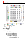
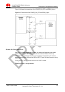
Figure 3-1 shows the sequence of pins on the 145-pin signal interface of the MC509
module.