


HUAWEI MC509 CDMA LGA Module
Hardware Guide
Description of the Application Interfaces
Issue 01 (2011-04-08)
Huawei Proprietary and Confidential
Copyright © Huawei Technologies Co., Ltd.
26
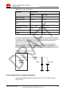
Through the Output Power Supply interface, the MC509 module can supply 2.6V and
1.8V power externally with an output current of 20mA (typical value) for external level
conversion or other applications.
If the MC509 module is in Sleep mode, the Output Power Supply interface is in the
low power consumption state (< 500μA). If the MC509 module is in Power Down
mode, the Output Power Supply is in the disabled state.
3.4 Signal Control Interface
3.4.1 Overview
The signal control part of the interface in the MC509 module consists of the following:
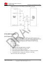
Power-on/off (POWER_ON_OFF) pin
Hardware reset (RESIN_N) pin
Network status LED (LED_STATUS/LED_MODE) pin
WAKEUP_IN Signal (WAKEUP_IN) pin
WAKEUP_OUT Signal (TBD)
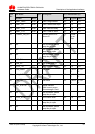
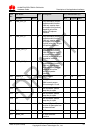
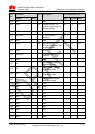
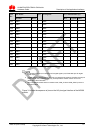
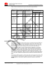
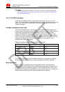
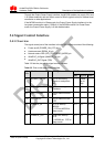
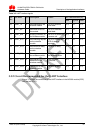
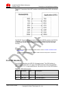
Table 3-5 lists the pins on the signal control interface.
Table 3-5 Pins on the signal control interface
Pin
No.
Pin Name
I/O
Description
DC Characteristics (V)
Min
Typical
Max
81
POWER_ON_OF
F
I
Pin for controlling
power-on and power-
off
-
Pulled
up on
chip
-
100
RESIN_N
I
Pin for resetting the
hardware
-0.3
1.8
2.1
91
LED_STATUS
I
Pin for network status
LED
-
-
-
101
LED_MODE
I
Pin for network mode
LED
-
-
-
11
WAKEUP_IN
I
H: DTE wakeup
MC509.
L: DTE set MC509 to
sleep mode.
-0.3
2.6
2.9
71
WAKEUP_OUT
O
H: MC509 wakeup
DTE
L: MC509 set DTE to
sleep mode.
-0.3
2.6
2.9