


HUAWEI MC509 CDMA LGA Module
Hardware Guide
Description of the Application Interfaces
Issue 01 (2011-04-08)
Huawei Proprietary and Confidential
Copyright © Huawei Technologies Co., Ltd.
38
The two audio I/O channels are completely different and thus have good performance
of resisting RF interferences. The routes on the printed circuit board (PCB) should be
placed in parallel with each other and should be short. The filter circuit on the two
sides should be symmetric. The differential signals should be close to each other.
The audio output signals in differential pairs and the audio input signals in differential
pairs should be separated effectively through ground. In addition, the audio signals
should be located away from the circuits of the power supply, RF, and antenna.
The first audio channel can be used for the handset without requiring any audio
amplifier. The output power for the differential ear output is typically 350mW for a full-
scale +3dBm sine wave into a 32-ohm speaker.
The second audio channel can be used for the hands-free without requiring any
audio amplifier. The output pins are configured differently, with a rated output of 500
mW into an 8Ω speaker.
Considerable current flows between the audio output pins
and the speaker, and thus wide PCB traces are recommended (20mils).
MC509 provides 2.2V power source and 1mA of bias current internally for the
microphones of both audio channels.
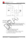
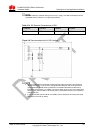
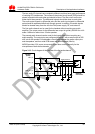
Figure 3-12 Circuit diagram of the interface of the first audio channel
Module
(DCE)
MIC1_P
MIC1_N
EAR_OUT_P
EAR_OUT_N
1nF
1nF
1nF
1nF
1nF1nF
ESD protection
Network
Connector