Page 9FM-4000
8 INSTALLATION
8.1 LOCATION
The radio can be mounted at any angle. Choose a mounting location that:
• is far enough from any compass to avoid any deviation in compass read-
ing due to the speaker magnet (see the compass safe distances in the
Safety Instructions)
• provides easy access to the front panel controls and rear connectors
• allows connection to a power source and an antenna
• has nearby space for installation of a microphone hanger
• the antenna must be mounted at least three feet from the radio
Note: To insure the radio does not affect the compass or the radio’s perfor-
mance is not affected by the antenna location, temporarily connect the radio in
the desired location and:
a. Examine the compass to see if the radio causes any deviation.
b. Connect the antenna and key the radio. Check to ensure the radio is
operating correctly by requesting a radio check.
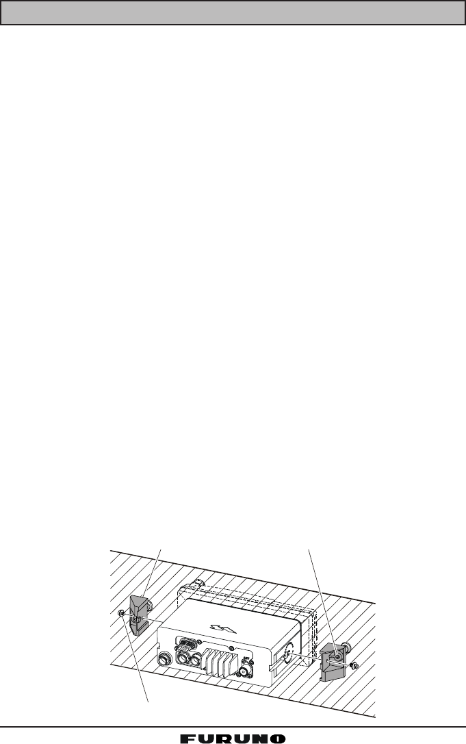
8.2 OPTIONAL MMB-84 FLUSH MOUNT INSTALLATION
1. Make a rectangular template for the flush mount measuring 2.9” H x 8.1”
W (72 x 205 mm).
2. Use the template to mark the location where the rectangular hole is to be
cut. Confirm that the space behind the dash or panel is deep enough to
accommodate the transceiver (at least six inches deep).
There should be at least 1/2 inch between the transceiver's heatsink and
any wiring, cables or structures.
3. Cut out the rectangular hole and insert the transceiver.
4. Fasten the brackets to the sides of the transceiver with the lock washer nut
combination so that the mounting screw base faces the mounting surface.
5. Turn the adjusting screw to adjust the tension so that the transceiver is
tight against the mounting surface.
Bracket
A
djusting Screw
Lock-washer nut combination


