


Installing a Liebert iCOM Unit-to-Unit Network
46
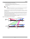
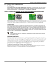
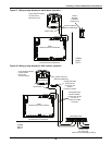
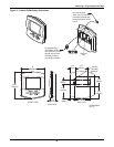
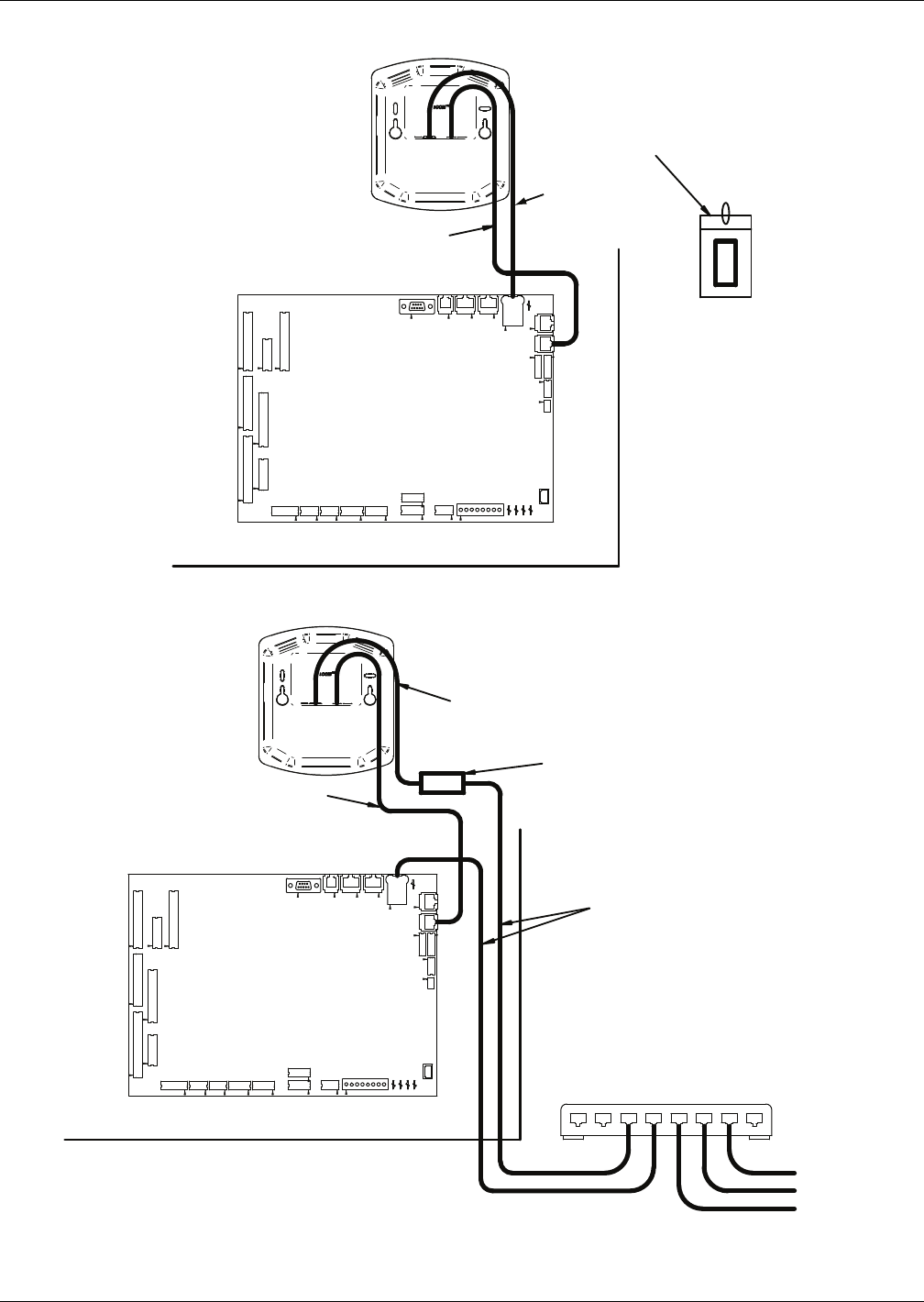
Figure 27 Wiring a large display for stand-alone operation
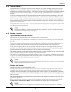
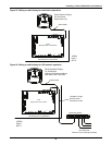
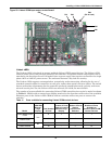
Figure 28 Wiring a large display for U2U network operation
182964
Page 2
Rev. 0
E1 E3
P8
P7
TB1
Large Graphics Display
On Unit Accent
Stand-Alone Unit
6-Wire Cable
P64 P66 P67
U2U CAN CAN
Liebert-
Supplied
Crossover
Coupler (F-F)
8-Wire Crossover
Ethernet Cable (Red)
iCOM
Microprocessor and I/O Board
P54
P22
P38
P39
P53
P52
P51
P4
E2 E4
Unit Electronics Compartment
P40
P32
P34
P33
P35
P36
P18
P65
P61
P63
P64
E5
P66
P13
P12
P11
P67
P43
E1
E3
E5
P4
182964
Page 2
Rev. 0
Large Graphics Display
On Unit Accent
Unit-to-Unit
Communications
8-Wire Crossover
Ethernet Cable (Red)
Unplug Red Cable
From P64 and
Connect to One
Side of
Crossover Coupler
2 Straight-through
Ethernet Cables-
Connect One to P64
and One to
Crossover Coupler
As Shown
Networking Switch
iCOM
Microprocessor and I/O Board
P22
P38
P39
P53
P52
P54
P51
TB1
E2
E4
P18
P65
P61
P63
P64
P66
P40
P8
P32
P34
P33
P35
P36
P7
P13
P12
P11
P67
P64 P66 P67
U2U CAN CAN
6-Wire Cable
Unit Electronics Compartment
To Other Units
(64 nodes total;
maximum of 32 input/output boards)
P43