


Teamwork
40
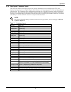
The number of available units is calculated like:
• In non-standby configuration: all units with fan on
• In typical standby function (no cascade): all units with fan on
• In cascade mode: all units that could operate (no alarm, which forces the unit to switch off, unit
not switched off, etc.)
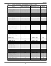
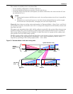
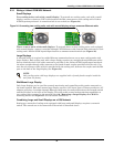
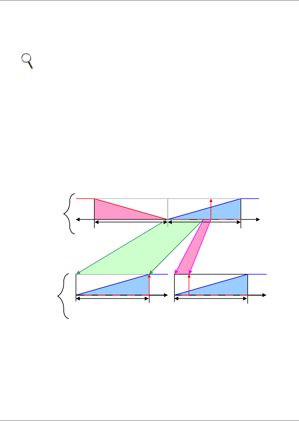
Figure 23 shows how two cooling units work together in Teamwork Mode 1. Since Unit 1 and Unit 2
are available to operate, the master unit, Unit 1, averages the temperature and humidity sensor read-
ings from each unit.
The master unit determines that a 60% call for cooling is required for the system. Since there are two
available cooling units, each unit makes up half of the system proportional band; Unit 1 handles 0-
50% system call for cooling and Unit 2 handles 51-100%. For every 1% system call for cooling, each
unit provides 2% of its total cooling capacity.
The 60% system call for cooling exceeds the 50% Unit 1 can provide, so Unit 1 operates at full capac-
ity. The remaining 10% system call for cooling (60% - 50% = 10%) is handled by Unit 2. Unit 2
responds by operating at 20% cooling capacity (50% ÷ 10% = 20%).
Figure 23 Teamwork Mode 1 with two cooling units
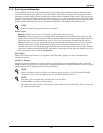
NOTE
1. Proportional actuators (chilled water valve, free-cooling actuator) are driven in parallel in
all units.
2. Changeover to second cooling source, low limit during dehumidification and low supply
limit control air local functions, managed from each unit independently.
Heating
-Temp
+
Temp
System Deviation : 60%
0%
Setpoint
½ Proportional Band½ Proportional Band
+ 100%- 100%
+ Temp
+ 100%+ 100%
0%
Setpoint
Unit2 Deviation: 20%Unit1 Deviation: 100%
0%
Setpoint
½ Proportional Band½ Proportional Band
Cooling Cooling
Cooling
System
Proportional
Band
+ Temp
Individual
Units