2.5 Installation of the Extension Cards
110 Installation Manual
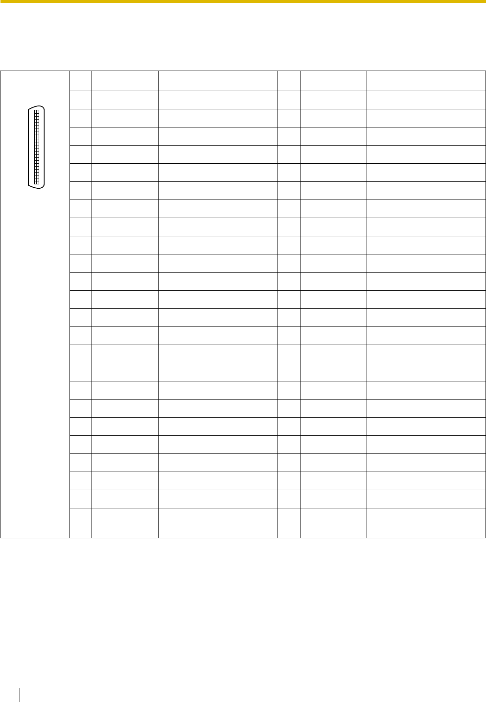
Pin Assignments
Amphenol Connector
No. Signal Name Function No. Signal Name Function
1 RA SLT Ring port 1 26 TA SLT Tip port 1
2 D2A PT Data port 1 (Low) 27 D1A PT Data port 1 (High)
3 Reserved – 28 Reserved –
4 RB SLT Ring port 2 29 TB SLT Tip port 2
5 D2B PT Data port 2 (Low) 30 D1B PT Data port 2 (High)
6 Reserved – 31 Reserved –
7 RC SLT Ring port 3 32 TC SLT Tip port 3
8 D2C PT Data port 3 (Low) 33 D1C PT Data port 3 (High)
9 Reserved – 34 Reserved –
10 RD SLT Ring port 4 35 TD SLT Tip port 4
11 D2D PT Data port 4 (Low) 36 D1D PT Data port 4 (High)
12 Reserved – 37 Reserved –
13 RE SLT Ring port 5 38 TE SLT Tip port 5
14 D2E PT Data port 5 (Low) 39 D1E PT Data port 5 (High)
15 Reserved – 40 Reserved –
16 RF SLT Ring port 6 41 TF SLT Tip port 6
17 D2F PT Data port 6 (Low) 42 D1F PT Data port 6 (High)
18 Reserved – 43 Reserved –
19 RG SLT Ring port 7 44 TG SLT Tip port 7
20 D2G PT Data port 7 (Low) 45 D1G PT Data port 7 (High)
21 Reserved – 46 Reserved –
22 RH SLT Ring port 8 47 TH SLT Tip port 8
23 D2H PT Data port 8 (Low) 48 D1H PT Data port 8 (High)
24-
25
Reserved – 49-
50
Reserved –
50 25
26 1


