


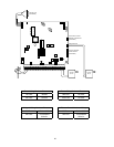
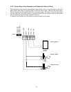
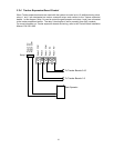

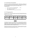

2.3.3 Controlling a Gate Operator and Two Pedestrian Doors (or Gates)
The diagram below shows how it is possible to control a gate operator and two pedestrian doors or
gates from the system. Relay 0 is typically used to control the gate operator and relays 1 and 2 are
used to control pedestrian doors and/or gates. Note that the electric strike and the magnetic lock are
powered from their own power supply. The relay 2 contact is set to either normally open (NO) for
electric strikes, or normally closed (NC) for magnetic locks by placing the relay 2 contact shorting bar
on either the NO or NC pins.
A variation of this diagram is for the system to control three doors, or two gate operators (entry and
exit) and a door, or three gate operators.
13 14 15 16 17
Relay 0
Relay 2 COM
Relay 2
Relay 1 COM
Relay 1 NO
Relay 1 NC
Relay 0 NC
Relay 0 NO
Relay 0 COM
Gate Operator
Electric Strike
Magnetic Lock
AND
AND
26