


1.2 MEMORY CHIP INSTALLATION
The telephone entry system is shipped with two memory chips packaged in a separate box inside the
shipping container. The memory chips must be installed for the telephone entry system to operate.
CAUTION!! Do not install the memory chips with power to the telephone entry system turned
on. Attempting to install the memory chips with power on will irrevocably damage the chips.
CAUTION!! The memory chips are a static sensitive component. Discharge any static
electricity from your hands by touching a proper ground device before removing the control
board. Handle the memory chips with care.
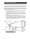
1. The large memory chip socket is colored black and is located in the center of the circuit
board. Be sure that the handle is in the un-locked position (pointing up). Be sure that
power to the telephone entry system is off.
2. Carefully insert the memory chip into the socket. The small half circular indentation on
the chip must be at the top. CAUTION: Installing the memory chip upside down will
cause permanent damage to the chip. Be sure that the memory chip is seated correctly
in the socket.
3. Move the lever on the chip socket to the locked position (down).
4. Install the small memory chip in the socket located at the bottom of the circuit board. The
small circular indentation on the chip must be at the top. CAUTION: Installing the
memory chip upside down will cause permanent damage to the chip. Be sure that the
memory chip is seated correctly in the socket. If it is necessary to remove this chip, use
a small bladed flat blade screwdriver to carefully pry the chip from the socket. Take extra
caution to be sure to not bend the pins on the chip.
17