


2.1 MAIN TERMINAL DESCRIPTION
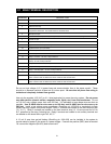
TERMINAL DESCRIPTION
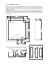
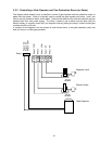
1 Phone Line Connection – 800 ft. maximum with 24 AWG wire; 1600 ft. maximum with 22 AWG wire.
2 Phone Line Connection – 800 ft. maximum with 24 AWG wire; 1600 ft. maximum with 22 AWG wire.
3 Earth Ground Only.
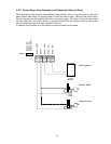
4 Switch Input. A closure between terminals 4 and 6 will cause the designated relay(s) to activate for the
programmed strike time. The Postal Switch is connected here.
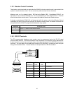
5 Microphone Input.
6 Common for switch input, microphone, speaker, AZ buttons, keyboard and battery negative.
7 Speaker Output.
8 Keyboard Data Input (not used).
9 Keyboard 5 VDC Power (not used).
10 Keyboard Clock Input (not used).
11 Z Button Input.
12 A Button Input.
13 Relay 2 Common – 30 Volt, 3 Amp maximum.
14 Relay 2 Contact (set for normally open or normally closed by the relay contact shorting bar on the circuit
board) – 30 Volt, 3 Amp maximum.
15 Relay 1 Common – 30 Volt, 3 Amp maximum.
16 Relay 1 Normally Closed – 30 Volt, 3 Amp maximum.
17 Relay 1 Normally Open – 30 Volt, 3 Amp maximum.
18 Back-up Battery POSITIVE (connect negative to terminal 6).
19 16 VAC Input Power – 20 VA minimum for 1803PC and 1815; 40 VA minimum for 1817.
100 ft. maximum with 18 AWG wire; 200 ft. maximum with 16 AWG wire.
20 16 VAC Input Power – 20 VA minimum for 1803PC and 1815, 40 VA minimum for 1817.
100 ft. maximum with 18 AWG wire; 200 ft. maximum with 16 AWG wire.
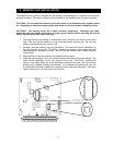
Do not run high voltage (115 V) power lines and communication lines in the same conduit. These
should be in separate conduits at least six (6) inches apart. Be sure that all phone line wiring is
twisted and completely isolated from ground.
Use only the supplied 16.5 VAC (or U.L. listed equivalent) to power the entry system. Do not power
any other devices (electric strikes, magnetic locks, lights, etc.) from this transformer. Do not
run 16 VAC entry system power lines over 200 feet. It is advisable to keep these wires as short as
possible. Use 18 AWG wire for wire runs up to 100 feet, and 16 AWG wire for wire runs up to
200 feet. Install a low voltage surge suppresser (DoorKing p/n 1878-010 or equivalent) to help
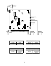
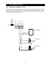
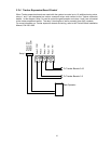
protect the entry system from power surges. Relay 1 contacts are located on the main terminal strip
(15, 16, 17). Relay 2 contacts are located on the main terminal strip (13, 14) and are set for N.O or
N.C. operation by the relay 2 shorting bar. Relay 0 contacts are located on an auxiliary terminal and
are labeled on the board left to right: NO, NC, C.
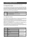
A 12 volt .8 amp hour gel-cell battery (DoorKing p/n 1801-008) can be installed in the system to
provide stand-by power in the event of a power outage. Connect the positive (RED) lead to terminal
18; connect the negative (BLACK) lead to terminal 6.
21