


61200375L1-1
TA 850
T1 RCU VoATM UIG/61200376L2-31A
Page 21 of 72
© 2001, ADTRAN, Inc. TA 850 User Manual
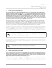
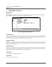
4. INSTALLING A MODULE
After installing the TA 850 Base Unit and connecting the required cables, you can install necessary modules.
Individual access modules insert from the front. A locking bar holds the modules in place for added security. Disen-
gaging the captured screw allows removal of the locking bar. All wiring connections terminate on the backplane.
The following step/action table tells how to install a module.
Refer to the next section, Configuring the TA 850, for general configuration instructions.
Refer to the appendices at the end of this document for information on usingthe TA 850 in specific
applications:
• Appendix D. Voice Gateway Quick Start Procedure (Voice Turn up) on page 65.
• Appendix E. RFC1483 Quick Start (IP Routing) on page 67.
• Appendix F. RFC1483 Quick Start (IP Routing with NAT) on page 69.
• Appendix G. RFC1483 Quick Start (Bridging) on page 71.
Remove the 20 Hz fuse before exposing backplane or accessing channel units.
Electronic modules can be damaged by static electrical discharge. Before handling modules, wear
an antistatic discharge wrist strap to prevent damage to electronic components. Place modules in
antistatic packing material when transporting or storing. When working on modules, always place
them on an approved antistatic mat that is electrically grounded.
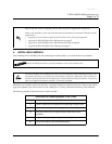
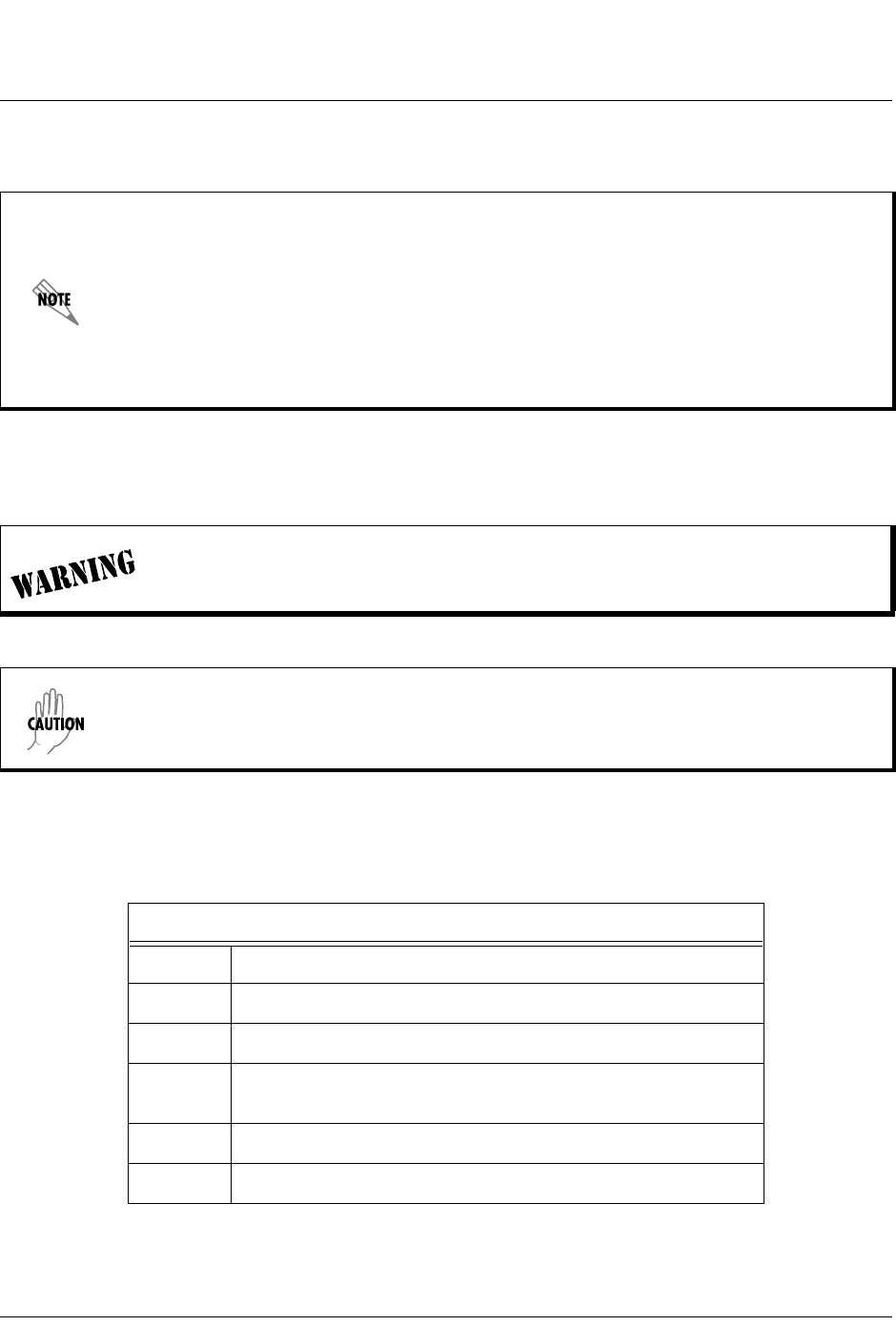
Instructions for Installing Module in the TA 850
Step Action
1
Hold the module by the faceplate while supporting the bottom side.
2
Align the module edges to the guide grooves for the designated slot.
3
Insert the module until the edge connector seats firmly into the
backplane.
4
Lock the unit in place by pushing in on the locking lever.
5
Connect the cables to the associated device(s).