


Total Access 600 Series System Manual Section 2 Engineering Guidelines
61200624L1-1B © 2004 ADTRAN, Inc. 27
Total Access 612/616/624
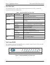
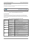
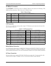
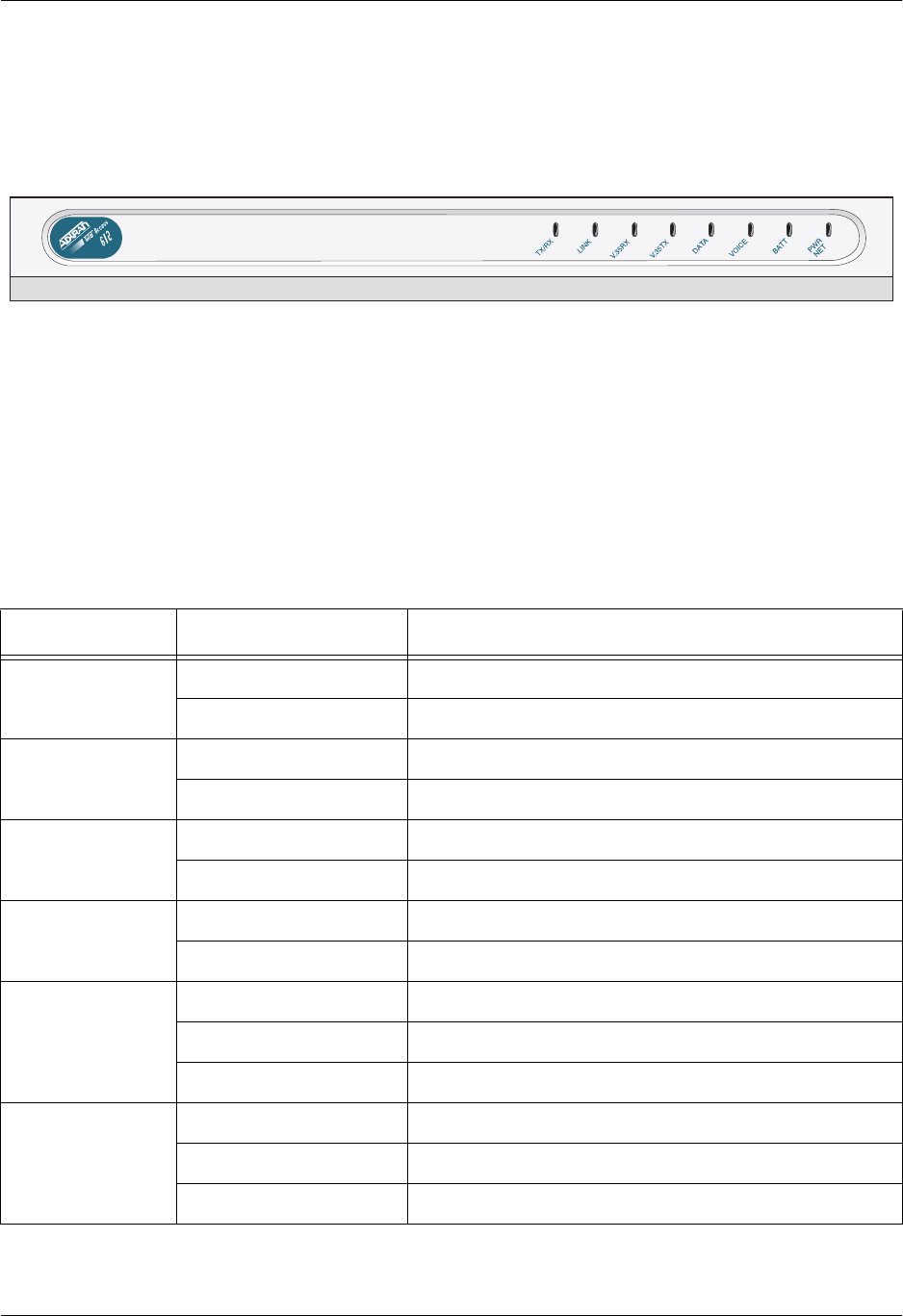
The front panels of the Total Access 612/616/624 systems are identical. Figure 3 shows the Total Access
612 front panel as a representative of all models.
Figure 3. Total Access 612/616/624 Front Panel Layout
Front Panel LEDs
The front panel provides eight status LEDs to monitor operation and activity. The LED functionality
varies based on product and software load (TDM versus ATM). Table 5 provides LED descriptions for
Total Access 612/616/624 systems employing TDM software, and Table 4 on page 26 lists ATM software
LED functionality.
Table 5. Total Access 612/616/624 TDM Front Panel LEDs
For these LEDs... This color light... Indicates that...
TX/RX
Off there is no data traffic on the LAN.
Green (blinking) there is data traffic on the LAN.
LINK
Off the physical link is down; no Ethernet connection.
Green (solid) there is link integrity on the LAN; the physical link is up.
V.35 RX
Off no data traffic is being received on the V.35.
Green (blinking) data is being received on the V.35.
V.35 TX
Off no data traffic is being transmitted on the V.35.
Green (blinking) data is being transmitted on the V.35.
DATA
Red (solid) the T1 is in red alarm or T1 sync loss has occurred.
Yellow (solid) the T1 is in test.
Green (solid) Layer 2 is up.
VOICE
Red (solid) the T1 is down.
Green (blinking) the phone is off hook.
Green (solid) the T1 is operational and the phone is on hook.