


E-36
Contrast – Sets the video contrast for this input. is
setting can be used to compensate for too much or too
little contrast in the source picture on this input when
compared with other video sources.
Colour – Sets the video colour saturation for this input.
is setting can be used to compensate for too much or
too little colour in the source picture on this input when
compared with other video sources.
Picture Mode – Sets how the video processor in the
AVR360 interprets the video on this input. Normally
the video processor automatically detects the original
source type and correctly sets either Video mode or
Film mode processing. In the unlikely event that the
video processor misinterprets the video type, resulting
in subtle picture artefacts, the video processor can be
manually forced into Video mode or Film mode. is
function should normally be set to Auto.
Edge Enhancement – Sharpens the picture from a
source on this input.
MPEG N.R. – Removes artefacts in overly compressed
digital video from a source on this input.
Noise Reduction – Removes random noise within the
picture from a source on this input.
Component Mode – Congures the current three-wire
high quality analogue video input for component (YUV)
video signals or RGB video signals. It is important
to match the setting to the incoming video format
otherwise the colours will be incorrect and the picture
may be unstable.
Options are Normal, RGsB and RGB+Sync.
< Normal: (default) the three-wire input is congured
for normal Component (YUV / YPbPr) analogue
video.
< RGsB: the three-wire input is congured for RGB
analogue video with video ‘sync-on-green’.
< RGB+Sync: the three wire input is congured for
RGB analogue video, with the video sync signal on
the composite input for the current named source.
You should typically select RGB+Sync if you are using
a standard SCART to 4-wire phono breakout cable to
connect an RGB SCART source.
NOTE: If RGB+Sync is selected, the S-Video and
Composite inputs cannot be selected as video inputs for
the current source.
Video Source – Selects the video signal connection for
this source. e default is HDMI; this setting must be
changed if another connection is used.
< HDMI: the unit is forced to use the HDMI video
input for this source.
< Component: the unit is forced to use the
COMPONENT/RGB video input for this source.
< S-Video: the unit is forced to use the
SVIDEO input
for this source.
< Composite: the unit is forced to use the
COMPOSITE
video input for this source.
Audio Source – Selects the particular connection type
for each input. e default is HDMI; this setting must be
changed if another connection is used.
Select from the list the audio type you are using on this
source.
<
HDMI: the unit is forced to use the HDMI audio
input for this source.
<
Digital: the unit is forced to use the optical (TOSLINK)
or coaxial (S/PDIF) digital audio input for this source
<
Analogue: the unit is forced to use the analogue
audio input for this source.
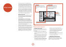
General Setup
General information and system controls.
Source Input – (Information only) e currently
selected input to which the settings below relate.
Incoming Format – (Information only) e format
of the digital audio stream connected to this input, if
present.
Incoming Sample Rate – (Information only) e
sample rate of the digital audio stream connected to this
input, if present.
Incoming Bit Rate – (Information only) e bit rate
of the digital audio stream connected to this input, if
present.
Dialnorm – (Information only) If a Dolby Digital audio
stream is connected to this input, this is the Dialogue
Normalisation setting requested by the stream.
Video Input – e currently selected video input. For
inputs that have video connections (e.g.
SAT, PVR etc),
audio and video inputs normally switch over together.
However, here you can temporarily select a dierent
video source for the current audio source. is feature
may be useful, for example, if you are watching a sports
game on satellite but on this occasion wish to listen to
the commentary on the radio instead. is temporary
override is reset when the input source is changed so
that the Video Input follows the Audio Input setting (or
the setting in the Video Inputs menu, if applicable).
Audio Compression – Allows selection of compression
which is ideal for late night listening. e compression
eect increases the volume of the quiet passages
and decreases the volume of the louder passages.
Compression only applies to Dolby soundtrack formats
that support this function (DTS is not supported).
< O: (default) no audio compression is applied.
< Medium: compression is applied so that loud
portions of a soundtrack are reduced in level.
< High: the maximum amount of dynamic range
compression is applied, so that the dierence
between loud and quiet portions of a soundtrack is
minimised.
is setting applies to all inputs when a relevant digital
audio stream is detected. It is stored in memory and
recalled each time the unit is powered up.
Balance – To alter the sound balance temporarily
between front le and right speakers. You can alter
the sound stage to either the le or the right by up to
6dB. Note that it is not possible to shi the audio signal
completely over to one channel. is function resets to
equal le/right balance when the input is changed.
PLII Dimension –
PLII Centre Width –
PLII Panorama –
ese allow the adjustment of the sound eld for Dolby
Pro Logic II Music mode decoding of two-channel
sources. ese setting apply to all inputs when PLII or
PLIIx Music decoding is selected. e settings are stored
in memory and recalled each time PLII or PLIIx Music
mode is selected.
< PLII Dimension: Allows the user gradually to
adjust the sound eld either towards the front or
towards the rear. Settings range from -3 to +3. We
recommend Dimension is set to 0 for normal use.
< PLII Centre Width: Controls the centre image
width.With Pro Logic decoding, dominant centre
signals come only from the centre speaker. If no
centre speaker is present, the decoder splits the
centre signal equally to the le and right speakers
to create a ‘phantom’ centre image. e Centre
Width control allows variable adjustment of the
centre image so it may be heard only from the
centre speaker; only from the le/right speakers as a
phantom image; or from all three front speakers to
varying degrees. We recommend Centre Width is set
to 3 for normal use.
< PLII Panorama: Extends the front centre image to
include the surround speakers for an exciting ‘wrap-
around’ eect with side-wall imaging.
Digital Output Freq. – Sets the sampling frequency of
the audio Analogue-to-Digital converter. is setting
applies to all inputs when analogue audio is being
processed (i.e. not Stereo Direct mode). It is stored in
memory and recalled each time the unit is powered up.
Maximum Volume – Limits the maximum volume
setting the system can be turned up to in the main zone.
is is a useful feature to prevent accidental overdriving
of low power-handling speakers (for example). It is
stored in memory and recalled each time the unit is
powered up.
Max On Volume – Limits the maximum volume the
system operates in the main zone when it is switched
on or comes out of Standby. e system comes on at
this stored volume setting if the last used (possibly very
loud) volume exceeds this value. It is stored in memory
and recalled each time the unit is powered up.
Display on time – Sets the time that the front panel
display remains illuminated aer receiving a command.
e default is always on.
Audio In iPod – If you have an iPod connected to the
AVR360 using an Arcam irDock or drDock, this control
allows you to set which audio input is used.
CEC Control – Enables or disables HDMI CEC control,
a system that allows devices connected with HDMI to
control other compatible connected devices.
ARC Control – Enables or disables the HDMI 1.4 Audio
Return Channel. is allows for television sound to be
sent back to the AVR360, via the “Display” input.
HDMI Audio To TV – Enables or disables the
transmission of HDMI audio from the HDMI output
connector. Enable this setting if you wish to be able to
listen using your TV speakers.
RS232 Control – Enables or disables RS232 control,
a system that allows control from various third-party
home automation systems.
Auto Setup
Auto Speaker Setup of your loudspeakers and subwoofer
(if present) is controlled by this menu. A full description
of how Auto Speaker Setup works is given on page E-33.
Remember to insert the calibration microphone into
the AUX input on the front panel and position the