


E-17
English
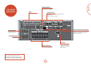
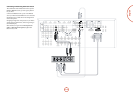
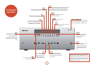
other
connectors
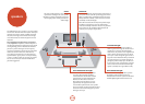
Data connectors
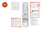
drDock/irDock
For use with an Arcam drDock or irDock accessory. See
page E-15 and the accessory documentation for details.
RS232 serial connector
Use with control devices having an RS232 serial
port (for example, Crestron and AMX touch screen
controllers).
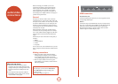
Network connector
is section deals with installation of the unit into an
existing home network. For
information on how to use the
AVR360’s network features,
the USB socket, and for a list
of supported le types, refer
to page E-45.
Networking is a large subject
and only the briefest guidelines are presented in
this handbook. Please contact your Arcam dealer
or specialist installer for more information about
introducing the AVR360 into your computer network.
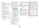
Ethernet
If an Ethernet cable is connected, the AVR360 will
automatically attempt to connect to your network.
You should use CAT5 cable plugged into the RJ45 socket
labelled
ETHERNET on the rear panel.
If your network uses static IP addressing rather than
DHCP, you will need to provide IP address, gateway,
DNS and proxy information. See page E-39 for
information on setting up the network.
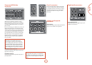
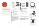
USB connector
e AVR360 can play les
stored on a USB mass storage
device, typically a pen drive,
but any USB device that
complies with the ‘mass storage
device‘ class is compatible.
e AVR360 only supports the direct connection of USB
devices and will not support devices connected through
a hub. If regular access to the
USB socket is required, you
may nd it convenient to use a USB extension lead.
See page E-45 for details of supported le types.
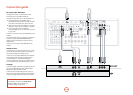
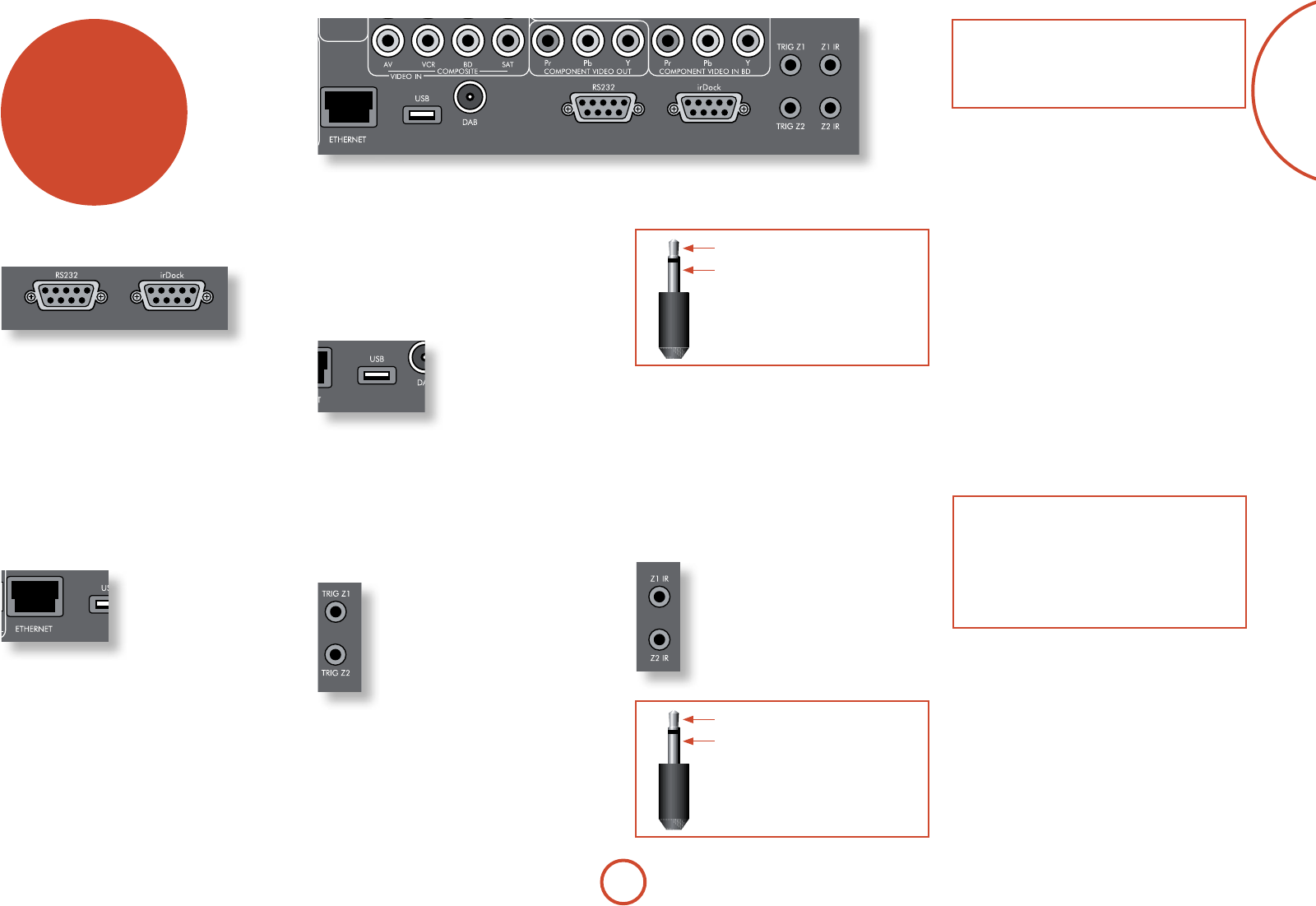
Trigger connectors
e trigger connectors (TRIG Z1 and
TRIG Z2) provide an electrical signal
whenever the AVR360 is switched on and
the relevant zone enabled.
e trigger signal can be used to switch
on and o compatible pieces of home
entertainment equipment, for example,
you could set up a trigger to turn on your
television and BD player whenever the
AVR360 was switched on.
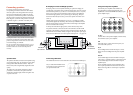
ere are two trigger output sockets on the AVR360,
each capable of outputting a 12V, 70mA switching
signal. e socket is designed for mono 3.5mm jacks: tip
is the trigger output, sleeve is ground.
tip: Trigger output
sleeve: Ground
TRIG Z1
Use for remotely turning on and o power amps or
source equipment for Zone1. On = 12V, O = 0V.
TRIG Z2
Use for remotely turning on and o power amps or
source equipment for Zone2. On = 12V, O = 0V.
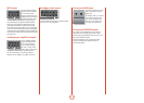
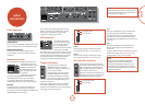
Infra-red (IR) connectors
e infra-red inputs (Z1 IR and Z2 IR) allow
the connection of external IR receivers, either
when the AVR360 front panel IR receiver is
fully or partially obstructed or to allow the
use of a remote control in Zone2.
ere are two IR inputs on the AVR360, each
designed for stereo or mono 3.5mm jacks. Tip
is the modulated signal, sleeve is ground.
tip: Modulated signal
sleeve: Ground
NOTE
Sockets referring to ‘Z2’ relate to connections used
in multi-room installation. For more information on
these connectors, see page E-46.
Z1 IR
is input is intended for use with a local IR receiver
when the front panel of the AVR360 is blocked.
Connecting an IR receiver to
Z1 IR will disable to front
panel IR receiver to prevent problems with multiple
commands if the front panel IR receiver is only partially
obstructed.
Z2 IR
is input is intended for use with an IR receiver in
Zone2 to allow remote control of AVR360 from a
second room.
A supplier of infra-red receivers and emitter accessories
and systems is Xantech. See www.xantech.com for
more information, or ask your Arcam dealer.
NOTE
e IR inputs on the AVR360 are designed for
modulated signals. If the external IR receiver
demodulates the IR signal, it will not work. Also
the AVR360 does not provide power for external
receivers on the IR jack, therefore an external power
source will be required.