7
Controls and Functions
INTRODUCTION
English
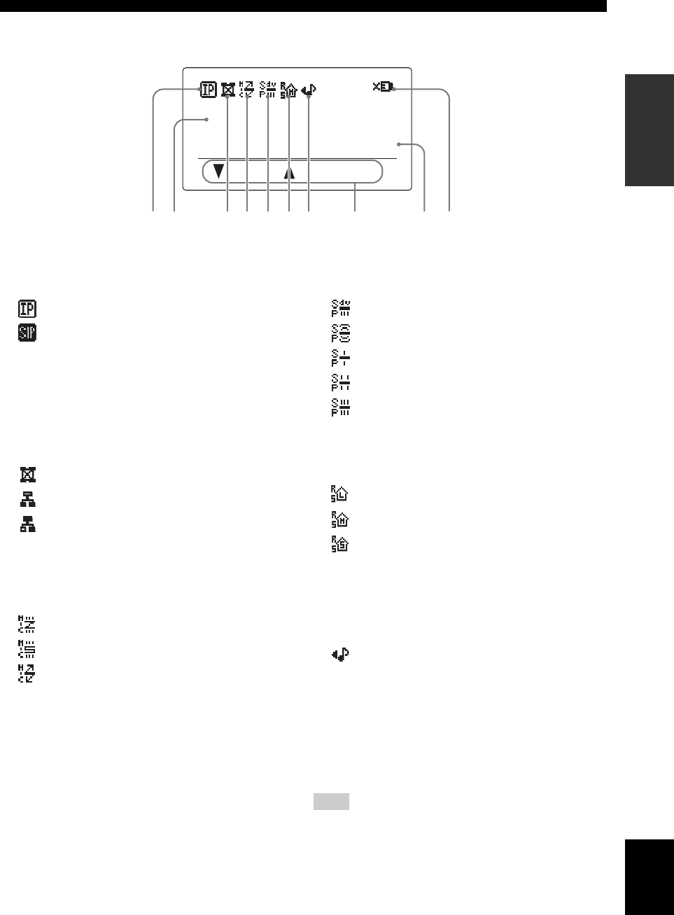
■ Display
1 Calling method indicator
The indicator shows the connection method used for the
current call.
• Call by designating the IP address.
• Call using a SIP server.
2 IP address
The IP address of this unit is displayed.
3 Connection mode indicator
The indicator shows the mode of connection with other
units. See “Configuring the connection mode” (page 27)
for details.
• Mesh mode
• Cascade Server mode
• Cascade Client mode
4 Microphone mode indicator
The indicator shows the current microphone mode. See
“Selecting the audio pickup area (microphone mode)”
(page 28) for details.
• Zone mode
• Spot mode
• Tracking mode
5 Speaker mode indicator
The indicator shows the current speaker mode. See
“Configuring the speaker mode” (page 29) for details.
• Divide mode
• Monaural mode
• Small Area mode
• Medium Area mode
• Large Area mode
6 Room size indicator
The indicator shows the current room size setting. See
“Configuring the room size” (page 30) for details.
• Large setting
• Medium setting
• Small setting
7 External input/output indicator
The indicator shows the current external input/output
setting. See “Configuring the external input/output
setting” (page 30) for details.
• (No indication): External input/output is not set.
• External audio equipment can be connected to
this unit.
8 Operation guide
The names of the currently available operations and their
keys are displayed.
9 Present time display
The present date and time are displayed.
The present time cannot be displayed in an environment in which
the SNTP server is not available. See “Setting Date and Time”
(page 37) for details.
0 Connection error indicator
The indicator is displayed when there is a problem with
the network connection. It is not displayed usually.
2006.05.15 09:48:20
Menu :Address
IP: 192.168.100.200
1 02 83 4 9567
Example of the initial display
Note
01EN_00_PJP-100H_UCGB.book Page 7 Wednesday, August 23, 2006 3:04 PM


