


11
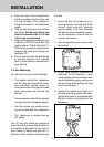
d. Insert one end of the handset cord
into the handset and the other end
into the left side of the telephone.
Place the handset in the telephone
cradle.
e. Plug the two long line cords into the
wall jacks.
Double check that you
have not reversed the L1/L2 and
L3/L4 cord connections.
f. Plug the AC power cord adaptor into
a standard 120V AC wall outlet. The
display shows “Check Clock & ID “.
Refer to the programming section to
program the clock and change the
extension ID.
g. Ensure that all cords are positioned
to prevent tripping and rubbing
which could create a potential elec-
trical hazard.
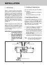
2.2 Wall Mounting
You will want to ensure the following:
• The location where the telephone
will be mounted should be away
from electrical cables, pipes, or
other items which may be punctured
when the screws are inserted into
the wall.
• The wall surface should be capable
of supporting the telephone weight.
• Use the screws and anchoring de-
vices provided with the telephone.
• The telephone is located near an
AC outlet.
Two (2) long line cords are provide to
meet various wall mounting conditions.
A template is provided at the back of
this manual to assist you with the in-
stallation of the telephone directly onto
the wall.
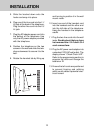
1. Insert the two (2) screws and an-
choring devices into the wall 3-5/8
inches apart vertically, allowing
approximately 3/16 inch between
the wall and screw heads for mount-
ing the telephone. Ensure that the
screws are secure.
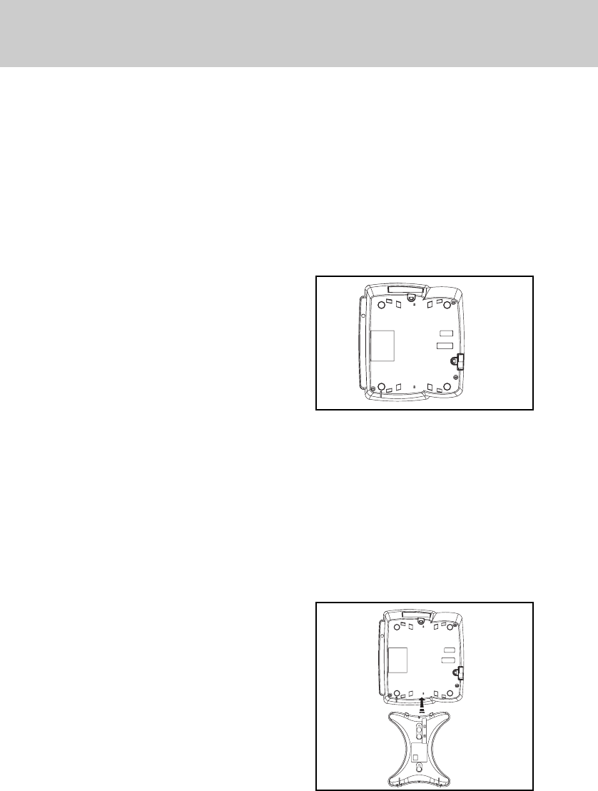
2. Turn the speakerphone over to view
the bottom.
3. If you have already installed the
desk/wall mount bracket in desk
mode, please remove the desk/ wall
mount bracket by gently moving one
tab at a time while pulling the peg
out of the tab hole.
4. Rotate the bracket and install it in
the wall mounting position by align-
ing the four holes on the bracket with
the four hooks on the bottom of the
telephone.
INSTALLATION