


Intercom User Station US2002 - 15
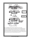
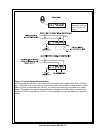
7. Shielded patch cable, 9-pin Male Dsub to 9-pin Female Dsub. Customer local pur
chase: available at Radio Shack, etc.
Note: All pins must be connected straight through: do not use an RS232 computer
cable!
8. Shielded patch cable, stereo miniplug to stereo miniplug. Customer local purchase.
Available at Radio Shack, etc.
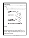
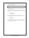
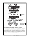
9. Shielded audio cable. Must have male 3-pin XLR connector at one end for connect
ion to the XP-USPG or XP-4PGM program inputs. Pin-out for program inputs is as
follows:
Pin 1: common
Pin 2: + program input
Pin 3: - program input
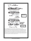
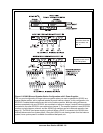
10. Shielded audio cable. Must have male 3-pin XLR connector at one end for connec
tion to the XP-USPG PA output. Pin-out for PA output is as follows:
Pin 1: common
Pin 2: + PA output
Pin 3: - PA output
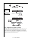
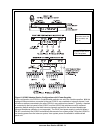
11. 18" (457 mm) CHANNEL OUTPUT cable, 15-pin Male Dsub to 15-pin Female
Dsub. One supplied with each XP-ES4000. (Optional component. See ES4000A User
Manual for connection information.)