


Intercom User Station US2002 - 14
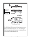
All Locally Powered Stations
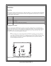
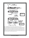
Any US2002 can be locally powered by connecting a PA-KP Local Power Supply. This is shown as
an option in Figures 4 through 12. A special case is an intercom system where all stations are
powered from local power supplies, with no central power supply. This is illustrated in Figure 13,
page 25.
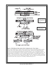
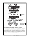
External Program Input and PA Output
Connections for external program input and PA output are shown in Figure 14, page 26.
ES4000A Expansion Station Connection (Optional Component)
Refer to the ES4000A User Instruction Manual for detailed connection information.
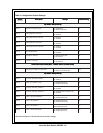
Cables
The numbers below correspond to the cable numbers in the connection drawings on the following
pages.
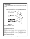
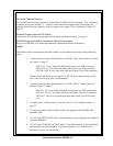
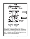
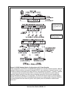
1. 1-channel intercom cable. Sold separately. Use Telex "ME" cables, below. Or, build
per Figure 15, page 27.
ME-25: 25' (7.6 m) cable with Male and Female 3-pin XLR connectors.
ME-50: 50' (15.2 m) cable with Male and Female 3-pin XLR connectors.
ME-100: 100' (30.4 m) cable with Male and Female 3-pin XLR connectors.
*When connecting from a power supply to a TW-7W, keep cables as short as pos
sible. Also, heavier gage wire is recommended.
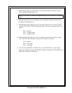
2. 2-channel intercom cable. Sold separately. Use Telex "ME /2" cables, below. Or,
build per Figure 15, page 27.
ME-25/2: 25' (7.6 m) cable with Male and Female 6-pin XLR connectors.
ME-50/2: 50' (15.2 m) cable with Male and Female 6-pin XLR connectors.
ME-100/2: 100' (30.4 m) cable with Male and Female 6-pin XLR connec
tors.
3. Y adapter cable. Sold separately. Use Telex CA-23-16. Or, build per Figure 15,
page 27.
4. 3 ft (0.91 m) speaker cable with RCA plugs. One supplied with each SPS-2001,
and SPK-2000.
5. 18" (457 mm) EXP IN/OUT cable, stereo miniplug to stereo miniplug. One supplied
with each ES4000A.
6. 18" (457 mm) CHANNEL OUTPUT cable, 15-pin Male Dsub to 15-pin Male Dsub.
One supplied with each ES4000A. (Optional component. See, ES4000A User
Manual for connection information.)