


nal jumper which routes the program either to the intercom channel only, or to
both the intercom channel and the US2000A headset or speaker (default setting).
Additionally, the program signal to the intercom channel may be turned on or
off via the US2000A front panel programming. There is also an internal pro-
gram interrupt DIP switch which selects either automatic program interrupt
when the station operator activates a channel's talk key, or no program interrupt
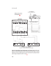
during talk. The ES4000A program inputs connector may be broken out to com-
mon 3-pin XLR audio cables using an optional XP-4PGM Breakout Panel.
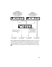
9. CHANNEL 3-6 OUTPUTS Connector: This connector provides the intercom chan-
nel audio input and output connections, as well as operating power when the
ES4000A is being powered from the intercom channels. Depending on the applica-
tion, this connector can connect to either a PS4000 Power Supply, or to an
XP-ES4000 Breakout Panel. Examples of both connections are provided in the wir-
ing diagrams which follow. A channel output cable is supplied with each ES4000A.
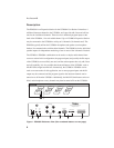
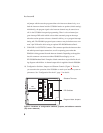
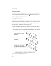
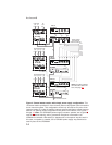
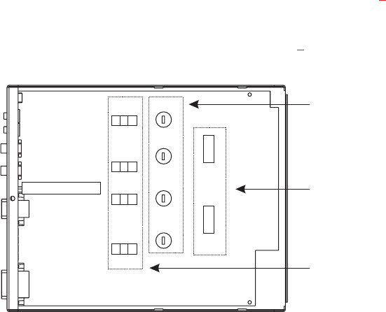
10. Configuration Switches, Jumpers and Sidetone Controls (Figure 2
). These let
you customize the operation of the ES4000A to match your intercom system re-
quirements. See “Configuration Pre-check”, page 7, for details.
6
Audiocom®
SW3
SW1
Ch 6
Ch 3
Ch 4
Ch 5
SW2
BAL/UNBAL
Sidetone Trimmers
J21
3 2 1
J15
3 2 1
J16
3 2 1
J18
3 2 1
DIP Switches
Program Listen Jumpers
Figure 2. Locations of configuration switches, jumpers, and sidetone controls.
(Top cover removed.)