


15
CHN 1
CHN 2
100-249 VAC 60/50 HZ
MADE IN USA
®
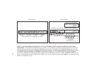
PS2000L
Channel 2 Power
Combine / Isolate Switch
set to Combine
CHN 1
CHN 2
100-240 VAC 60/50 HZ
MADE IN USA
®
INPUT 1
SPEAKER
INPUT 2
LINE LEVEL
1 VRMS
12-15 VDC
+
-
1
SPEAKERS
PROGRAM
INPUTS
2
LINE LEVEL
1 VRMS
P.A.
EXP
OUT
CHN 2
VOL
PGM 2
VOL
PGM 1
BAL - OUT
UNBAL - IN
PUSH PUSH
CHN 1
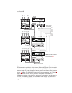
To ½ of stations
on channel 2
To ½ of stations
on channel 1
To ½ of stations
on channel 2
To ½ of stations
on channel 1
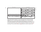
SPS2000A
Channel 1 Power and
All-Channel Speaker
Combine / Isolate Switch
set to Combine
Note:
US2000A Internal
DIP switches set
for monaural
operation (default)
1
1
1 1 1
1
4
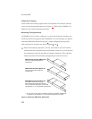
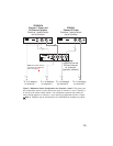
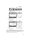
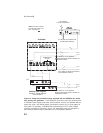
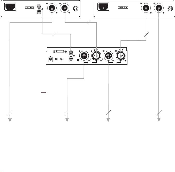
Figure 7. Maximum Power Configuration for Channels 1 and 2. This power sup-
ply configuration should only be used at one point in channels 1 and 2. Typically, it
is set up at the central master station. This configuration permits about twice as
many remote stations on channels 1 and 2 than the configuration shown in Figure
6
. Note: A PS2000L may be substituted for the SPS2000A for headset-only opera-
tion.
Note: For further informa-
tion about the cable num-
bers, see page 22.