


11
FRONT OF RACK
BACK OF RACK
BOP-1000 WITH 1 XP-USPG AND 1 XP-4PGM
SPARE
XP-USPG
US2000A (CH 1/2)
2 ES4000A'S
(CH 3-6 AND CH 7-10)
SPS2000A (CH1/2 POWER)
XP-4PGM XP-4PGM
SPS2000A
1
2
Combine
Isolate
Reset
Volume
®
US2000A
Mic Kill
Headset
PA
Panel Mic
Vox
All Talk
Listen Listen
Call Call
12
Talk Talk
Volume
®
PS-4000
3
4
1
2
Reset
®
ES4000A
Listen Listen
Call Call
56
Talk Talk
Listen
Call
4
Talk
Listen
Call
3
Talk
®
PS-4000
3
4
1
2
Reset
®
ES4000A
Listen Listen
Call Call
56
Talk Talk
Listen
Call
4
Talk
Listen
Call
3
Talk
®
PS4000 (CH3 -6POWER)
PS4000 (CH7 -10POWER)
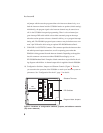
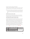
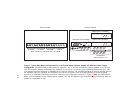
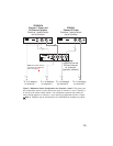
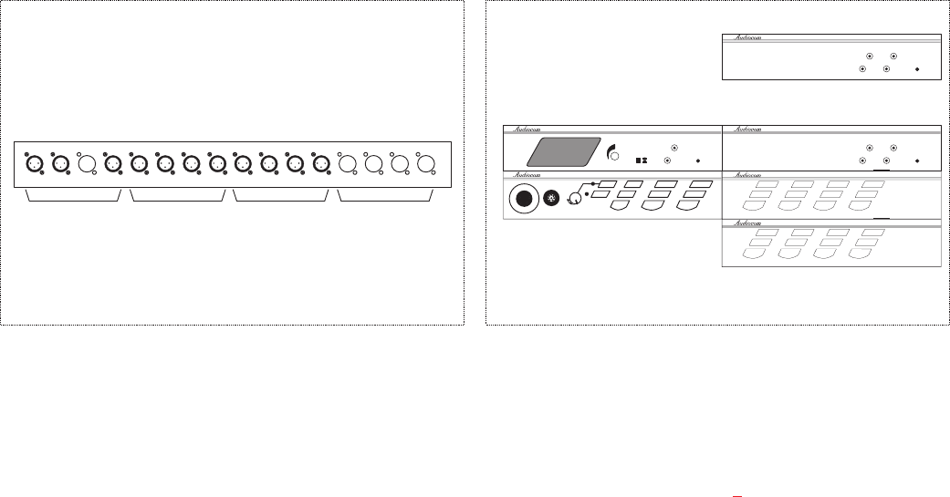
Figure 4. Typical Rack Mount Configuration for a 10-Channel Master Speaker Station with Minimum Power Supply
Configuration. The SPS-2000A provides power for channels 1 and 2, and also provides the listening speaker for all 10 chan-
nels. A microphone must be connected to the US2000A for talk on the 10 channels. Each PS4000 provides power for 4 inter-
com channels and also interfaces an ES4000A to the intercom channels. The XP-USPG interfaces 2 external program inputs to
the US2000A, and also interfaces the US2000A to an external PA system. Each XP-4PGM interfaces 4 external program
sources to an ES4000A. Connections and further details for this configuration are shown in Figure 6
. Note: An additional rack
space is shown between the two PS4000 power supplies. This may be required to prevent power supply overheating when the
ambient air temperature is high.