


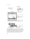


24
Audiocom®
Pair 1
Pair 1
Pair 1
Pair 2
Pair 2
Pair 2
Pair 3
Pair 3
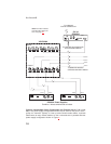
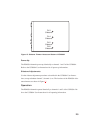
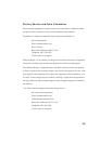
TYPICAL 2-CHANNEL CABLEWIRING
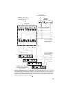
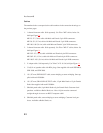
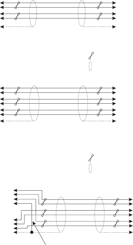
“Y”CABLE WIRING
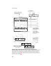
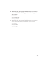
TYPICAL 1-CHANNEL CABLEWIRING
CableType:22AWG Stranded, 3-Pair Twisted-wire, with Shield
Pin 3: Channel 1 Audio / Power
Pin 4: Channel 1 Audio / Power
Pin 5: Channel 2 Audio / Power
Pin 6: Channel 2 Audio / Power
: Earth ground
Connector Type:6-Pin XLR Audio (Neutrik only, not compatible with 6-pin Switchcraft)
Pin 1: Channel 1 & 2 Common
Pin 2: No connection
*
Shield
CableType:22AWG Stranded, 2-Pair Twisted-wire, with Shield
Channel Audio / Power
Pin 3: Channel Audio / Power
: Earth ground
Connector Type:3-Pin XLR Audio (Neutrik or Switchcraft)
Pin 1: Common
Pin 2:
*
Shield
*
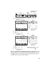
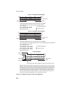
Standard cables are generally constructed using a male connector at one end and a
female connector at the other end.This allows several cables to be interconnected to
create longer cable runs.
Audiocom power supplies use a 3-pin male Neutrik connector for
each channel. Audiocom wallplates use male Neutrik connectors.
Audiocom master stations, speaker stations and belt packs
also typically provide both a male and female Neutrik connector for each intercom
channel.This permits loop-through connection of several intercom stations using the
standard cables.
Use second drain wire if available, or add an extra section of wire.
Ch1
Ch2
Denotes twisted pair.
Denotes twisted pair.
Denotes shield.
Denotes shield.
33
3
3
22
2
2
1
1
1
Shield Shield
Case
Shield
44
4
33
3
66
6
55
5
1
1 (Both wires)
1 (Both wires)
1 (Both wires)
Shield Shield
Shield
Figure 14. Audiocom intercom cable wiring diagrams