


14
Audiocom®
CH 1
CH 2
CH 3
CH 4
CH 5
CH 6
CH 7
CH 8
CH 9
CH 10
CHN 3 CHN 4
CAT.NO.9000-7336-00 MADE IN USA
CHN 1 CHN 2
CONNECT TO ES-4000
CLASS 2 WIRING 2A 24VDC
CH 7-10
PS4000
ES4000A
12-15 VDC
+
-
3
SPEAKERS
PROGRAM
INPUTS
4
LINE LEVEL
1 VRMS
EXP
OUT
CAN 3-6 OUTPUTS
EXP
IN
5
6
3456
PGM VOLUME
BAL-OUT
UNBAL-IN
Telex
®
CHN 3 CHN 4
CAT.NO.9000-7336-00 MADE IN USA
CHN 1 CHN 2
CONNECT TO ES-4000
CLASS 2 WIRING 2A 24VDC
CH 3-6
PS4000
ES4000A
12-15 VDC
+
-
3
SPEAKERS
PROGRAM
INPUTS
4
LINE LEVEL
1 VRMS
EXP
OUT
CAN 3-6 OUTPUTS
EXP
IN
5
6
3456
PGM VOLUME
BAL-OUT
UNBAL-IN
Telex
®
12-15VDC
+
-
1
SPEAKERS
PROGRAM
INPUTS
2
LINE LEVEL
1VRMS
P.A.
EXP
OUT
CHN 2
VOL
PGM 2
VOL
PGM 1
BAL - OUT
UNBAL - IN
PUSH PUSH
CHN 1
US2000A
CHN 1
CHN 2
100-240 VAC 60/50 HZ
MADE IN USA
®
INPUT 1
SPEAKER
INPUT 2
LINE LEVEL
1VRMS
CH 1-2
SPS2000A
CH 1-2
XP-USPG
PA
OUT
PGM
1 IN
PGM
2 IN
BACK
FRONT
CH 3 - 6
XP-4PGM
BACK
FRONT
PGM
3 IN
PGM
4 IN
PGM
5 IN
PGM
6 IN
CH 7 - 10
XP-4PGM
BACK
FRONT
PGM
7 IN
PGM
8 IN
PGM
9 IN
PGM
10 IN
TO ANOTHER ES4000A
TO BELT PACKS
AND REMOTE
MASTER STATIONS
111111
9 999
1 1
1
1
1
9 99
9 109
1
4
6
6
5
5
5
7
9
8
7
7
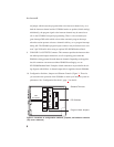
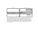
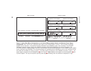
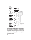
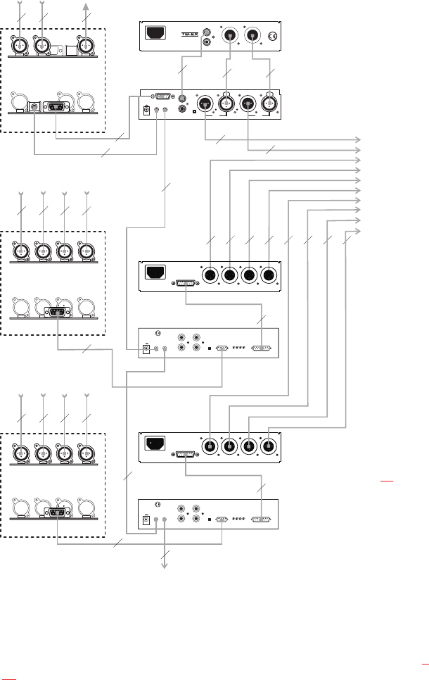
Figure 6. Central master station with simple power supply configuration. This
10-channel station provides all of the channel power and program input connections
for the intercom system. This configuration should only be used at one point in the
intercom system. It is ideal for smaller intercom systems with fewer remote intercom
stations. For optional power configurations that permit more stations, see Figures 7
through 10. Note: The SPS2000A power supply includes a speaker and is typically
used for intercom listening, with a gooseneck microphone connected to the
US2000A for talk-back. Alternatively, a headset with a microphone may be used. In
this case, no speaker is needed, and a PS2000L power supply may therefore be
used in place of the SPS2000A.
Note: For further informa-
tion about the cable num-
bers, see page 22.