


21
+
-
INPUT1
INPUT2
12-15 VDC
BAL
®
12-15 VDC
+
-
1
SPEAKERS
PROGRAM
INPUTS
2
LINE LEVEL
1 VRMS
P.A.
EXP
OUT
CHN 2
VOL
PGM 2
VOL
PGM 1
BAL - OUT
UNBAL - IN
PUSH
PUSH
CHN 1
SPK2000
CH 1-2 US2000A
XP-ES4000
12-15 VDC
+
-
3
SPEAKERS
PROGRAM
INPUTS
4
LINE LEVEL
1 VRMS
EXP
OUT
CAN 3-6 OUTPUTS
EXP
IN
5
6
3456
PGM VOLUME
BAL-OUT
UNBAL-IN
Telex
®
FRONT
BACK
CH 3-6 ES4000A
PUSH
PUSH
PUSH
PUSH
CH 1
CH 2
CH 6
CH 5
CH 4
CH 3
+
-
INPUT1
INPUT2
12-15 VDC
BAL
®
12-15 VDC
+
-
1
SPEAKERS
PROGRAM
INPUTS
2
LINE LEVEL
1 VRMS
P.A.
EXP
OUT
CHN 2
VOL
PGM 2
VOL
PGM 1
BAL - OUT
UNBAL - IN
PUSH
PUSH
CHN 1
SPK2000
CH 1-2 US2000A
XP-ES4000
12-15 VDC
+
-
3
SPEAKERS
PROGRAM
INPUTS
4
LINE LEVEL
1 VRMS
EXP
OUT
CAN 3-6 OUTPUTS
EXP
IN
5
6
3456
PGM VOLUME
BAL-OUT
UNBAL-IN
Telex
®
FRONT
BACK
CH 3-6 ES4000A
PUSH
PUSH
PUSH
PUSH
CH 1
CH 2
CH 3
CH 4
CH 5
CH 6
PS-L PS-L
PS-L
PS-L
PS-L
PS-L
TO ADDITIONAL
LOCALLY POWERED
INTERCOM STATIONS
TERMINATION PLUGS
TERMINATION
PLUGS
1
1
1
1
1
1
6
1
1
6
4
4
1
1
1
1
5
5
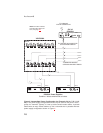
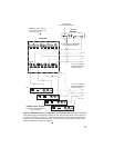
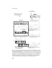
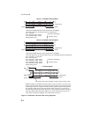
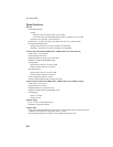
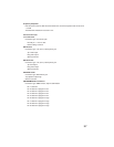
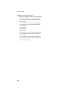
Figure 13. Using termination plugs for all dry-line connection. In this example, all components use local power supplies,
and no power is supplied on the intercom channels. All stations may be operated over a much greater distance than is possi-
ble when using powered channels. Important: there should only be one termination plug used in each channel.
Note: For further informa-
tion about the cable num-
bers, see page 22
.