


Connection Notes
•
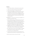
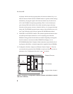
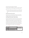
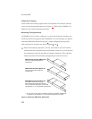
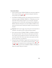
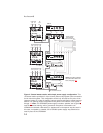
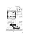
Typical connections for the US2000A, ES4000A and various power supplies are
shown starting with Figure 6, page 14. Select the configuration which most
closely matches your intended usage.
•
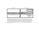
The US2000A and ES4000A normally draw operating power from the intercom
channel power supplies (SPS2000A, PS2000L, etc.). Alternatively, you can use
optional PS-L Wall-pack Power Supplies. If you are using PS-L Wall-packs,
connect them to the 12-15 VDC jacks on the back panels of the US2000A and
ES4000A. When PS-L Wall-packs are used, the US2000A / ES4000A will not
draw power from the intercom channel power supplies, leaving more power for
belt packs.
☞
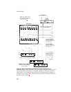
Important: The PS-L power supply only provides power for the station that it is
connected to. You cannot use a PS-L to power the intercom channels!
• Never connect more than 1 SPS2000A, PS2000L, or PS4000 Power Supply to
the same intercom channel. This will cause poor audio quality and increased
noise. Typically, all power supplies are located at a central location, such as a
central master station. This lets the central master station operator turn off the
intercom system when it is not being used.
•
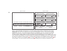
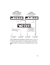
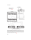
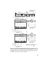
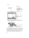
Termination Plugs: The ES4000A is supplied with 2 termination plugs for spe-
cial applications where 1 or more channels are unpowered. Figures 12, page 20
and 13, page 21 show examples of how to use these plugs. If all of your inter-
com channels will be powered from an SPS2000A, PS2000L, or PS4000 power
supply, the termination plugs are not needed.
13