


Putting the receiver into operation
11
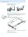
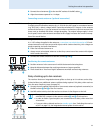
̈ Connect the rod antennas ƿ to the two BNC sockets of the BNC cables .
̈ Align the antennas upwards in a V-shape.
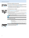
Connecting remote antennas (optional accessories)
̈
Connect two remote antennas to the BNC sockets ƻ and ƾ.
Positioning the remote antennas
̈
Position antennas in the same room in which the transmission takes place.
̈ Keep the distance between the receiving antennas as large as possible.
̈ There should be a “free line of sight” between transmitter and receiving antennas.
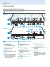
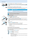
Daisy-chaining up to ten receivers
The receivers feature an integrated antenna splitter so that up to 10 receivers can be daisy-
chained without any additional antenna splitters being required. Only daisy-chain receivers
from the same frequency range (see page 4).
̈ Connect the two supplied rod antennas or two remote antennas (optional accessories) to
the BNC sockets ƻ and ƾ of the first receiver.
̈ Use BNC cables to daisy-chain the receivers as shown in the diagram on the left.
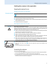
CAUTION! Danger of damage to the antennas
To supply an active direction antenna (e.g. A 3700 for the UHF range) or an antenna booster
(e.g. AB 3700), a direct voltage (which cannot be switched off) is output via the antenna
sockets of the receiver. If you use antennas from other manufacturers, take into account that
these must be installed with direct voltage decoupling. The output voltage supply is short
circuit-proof, but an active antenna connected to this supply increases the current consump-
tion of the overall device.
CAUTION! Danger of short-circuit due to uninsulated antennas!
A 11 V DC voltage is applied to the antennas – even when you switch the receiver off! If unin-
sulated antennas come into contact with objects which conduct electricity, this voltage can
produce sparking and audio interference.
̈ Either use insulated antennas or
̈ always mount uninsulated antennas so that they cannot come into contact with objects
which conduct electricity.
RF IN RF INRF OUT
ANT II ANT I
ƻƾ
RF IN RF INRF OUT
ANT II ANT I
RF IN RF INRF OUT
ANT II ANT I
RF
IN
ƻ
ƾ
• To supply an active directional antenna, a direct voltage (which cannot be
switched off) is output via the antenna sockets ƻ and ƾ of the receivers.
• In order to obtain a good reception, we recommend not to daisy-chain more than
10 receivers.
• If you set a daisy-chained receiver to standby mode (see “Switching the receiver
on/off” on page 13), the integrated antenna splitter remains active.