


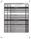
9
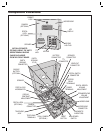
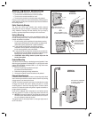
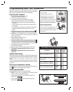
Access Relay Wiring
The access relay controls access devices, such as a door strike, magnetic
lock, automatic door, barrier gates, or automatic sliding gate. The RELAY
indicator displays the status of the relay.
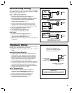
Door or Pedestrian Gate Control
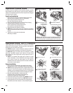
1. Install a low voltage electric door strike or magnetic lock
as a locking device for the door or pedestrian gate.
2. Install the power supply or transformer for the locking device. DO
NOT POWER THE AE-100 FROM THIS POWER SUPPLY.
3. Connect one wire from the power supply to
one wire from the locking device.
4. Route two wires between the locking device and the AE-100.
Connect one wire to the remaining wire of the locking device.
Connect the other wire to the remaining wire of the power supply.
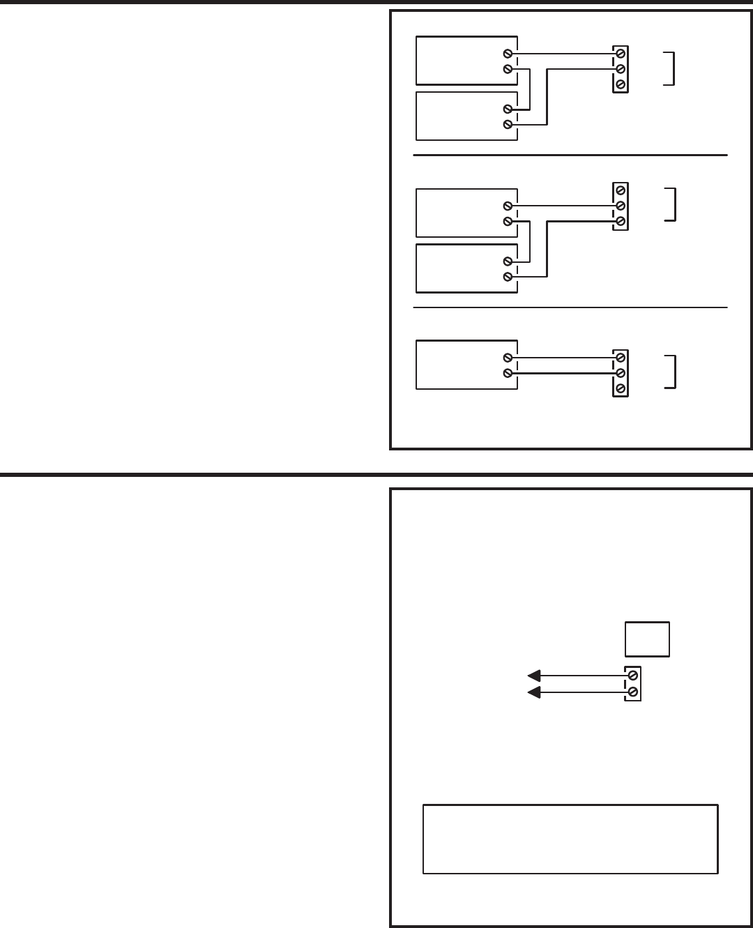
5A. For a door strike, connect the wires to the AE-100
access relay COM & N.O. terminals.
5B. For a magnetic lock, connect the wires to the
AE-100 access relay COM & N.C. terminals.
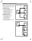
Gate Control
1. Route two wires between the gate and the AE-100.
2. Connect the gate operator’s OPEN terminals to the
AE-100 access relay COM & N.O. terminals.
✦ NOTE: For operator wiring specifi cs, refer to the gate operator’s
wiring diagram
.
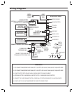
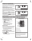
Telephone Wiring
For telephone entry and programming, the AE-100 connects to a standard
telephone line. A dedicated telephone line is required.
✦ NOTE: For multiple-unit installations, also refer to the next
section.
Important Telephone Wiring Tips
DO NOT ROUTE TELEPHONE AND AC WIRING INSIDE THE •
SAME CONDUIT. Route all telephone wires inside a dedicated
conduit that is at least six inches away from any AC line wiring.
All telephone wiring must be made on the “building” side of the •
telephone company’s demarcation device (the terminal block
where the telephone line connects to the building).
If any security system or personal alert system at the installation is •
connected to the telephone line, be sure that it is connected to the
line ahead of the AE-100 using a RJ-31X or RJ-38X interface.
Use only high-quality telephone wire. All telephone wire should be •
twisted-pair with a minimum size of 24 AWG.
Typical Telephone Wiring
1A. If using the AE-100 modular connector for the telephone
connection, connect a double-ended modular cable
between the AE-100’s TELEPHONE jack and the modular
telephone jack wired to the installation’s telephone line.
1B. If using the AE-100 terminal block for the telephone
connection, connect the two telephone wires to the
two screw terminals (polarity either way).
N.C.
COM
N.O.
ACCESS
RELAY
RELAY RATING:
10 AMPS MAXIMUM @ 30 VOLTS AC
7 AMPS MAXIMUM @ 30 VOLTS DC
TYPICAL DOOR STRIKE HOOKUP
TYPICAL MAGNETIC LOCK HOOKUP
TYPICAL AUTOMATIC GATE HOOKUP
ELECTRIC
DOOR
STRIKE
DOOR
STRIKE
POWER SUPPLY
N.C.
COM
N.O.
MAGNETIC
DOOR
LOCK
DOOR
LOCK
POWER SUPPLY
N.C.
COM
N.O.
GATE
OPERATOR
OPEN
ACCESS
RELAY
ACCESS
RELAY
TELEPHONE
TERMINALS
TELEPHONE
JACK
TO THE INCOMING
DEDICATED
TELEPHONE LINE
CONNECT THE TELEPHONE LINE
TO EITHER THE SCREW TERMINALS
OR THE RJ-11 TELEPHONE JACK
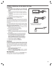
TO PREVENT LINE HUM, DO NOT ROUTE THE TELEPHONE
LINE AND THE AC WIRING INSIDE THE SAME CONDUIT!
CAUTION!
TELEPHONE LINE POLARITY
IS NOT CRITICAL