


7
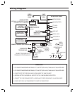
Entry System Mounting
The AE-100 cabinet is designed to be mounted three ways:
The unit can be mounted directly to a wall or fl at surface. •
The unit can be mounted recessed into a wall. •
The unit can be mounted on a standard goose-neck pedestal. •
Choose a well lit location near the controlled opening. Wiring access for
power, telephone, earth ground, and access output must be available to
the mounting location.
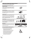
Static Electricity Warning
The unit’s main circuit board contains static sensitive electronic
components that can be damaged or destroyed by static discharges
during installation. Discharge the static electricity from your body by
touching a grounded object before touching the unit’s circuit board.
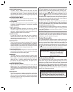
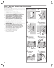
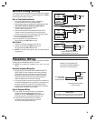
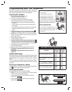
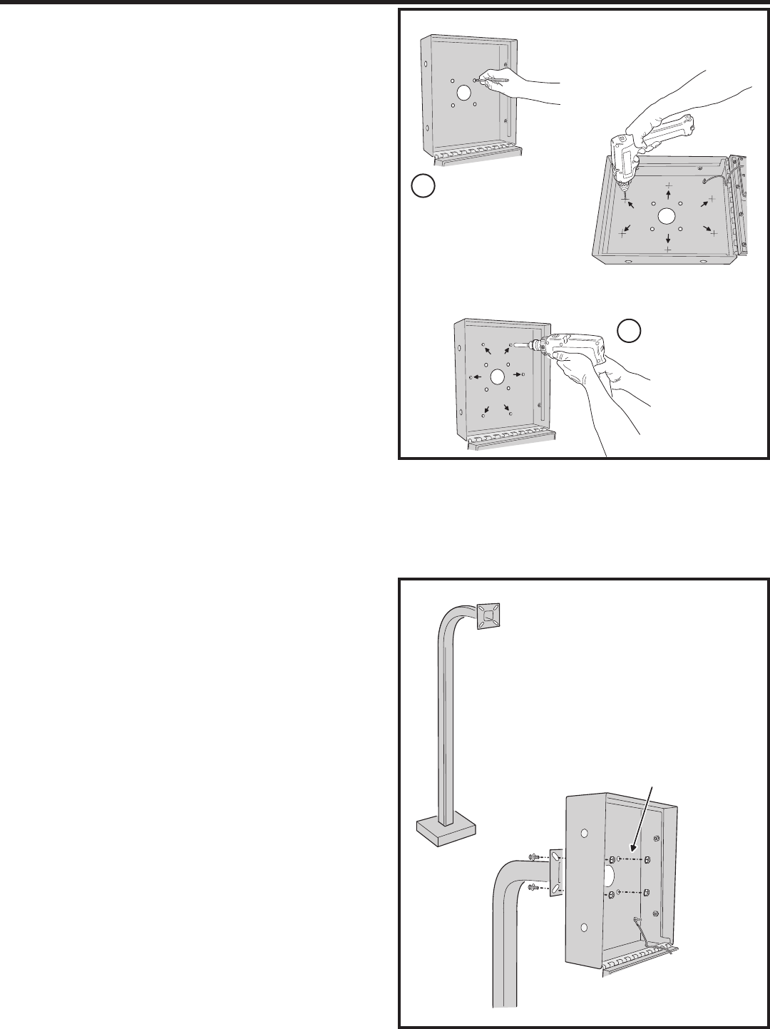
Surface Mounting
The cabinet can be mounted on a wall or any suitable fl at surface. The
four 3/8” mounting holes or any of the six self-drill locations can be used
to attach the cabinet to the surface.
1. For wall mounting, hold the cabinet at the approximate mounting
location where the display will be about eye level or slightly above
(follow ADA mounting requirements in public installations).
2A. If using the 3/8” mounting holes, mark the four mounting
hole centers. Drill as required. Use the appropriate fasteners
for the mounting surface to secure the cabinet.
2B. If using the self-drill mounting holes, choose the correct size bit for
the fasteners and drill the cabinet as required. Use the appropriate
fasteners for the mounting surface to secure the cabinet.
✦ CAUTION!: After drilling, remove any metal chips from the
inside of the cabinet.
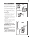
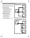
Pedestal Mounting
The cabinet can be mounted on a standard goose-neck pedestal. Linear
offers two types of pedestals. The Model GNC-1 is a 42” high curb-mount
pedestal (P/N ACP00906), the Model GNB-1 is a 72” high burial-mount
pedestal (P/N ACP00907).
1. Fish the wiring through the pedestal and install
the pedestal at the desired location.
2. Route the wiring through the large cabinet hole.
3. Use security hardware to attach the cabinet to the pedestal.
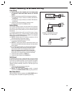
External Alarm Contacts
In installations where vandalism is a concern, an internal normally closed
alarm contact may be added as a tamper switch to the AE-100 providing
a trigger source for an external alarm panel.
If the AE-100 cabinet is opened for any reason, the internal alarm contact
will trigger the external alarm panel, reporting the alarm to a central
monitoring station or other alarm reporting location. The alarm contact
must be a UL Listed alarm switch using either a magnetic reed switch or
plunger operated microswitch.
Insure that the additional switch components do not interfere with the
door lock, optional CCTV camera, or other wiring internal to the AE-100.
✦ NOTE: Be sure that the locked AE-100 cabinet door makes a solid
connection to the alarm switch so that false alarms do not occur if
the unit is vibrated or shaken by the wind.
The typical location for the tamper switch is in the upper right corner of
the AE-100 cabinet.
1
MARK THE FOUR
3/8" MOUNTING HOLES
OR
ATTACH THE CABINET
WITH APPROPRIATE
HARDWARE FOR THE
MOUNTING SURFACE
DRILL THE CABINET AT THE
SIX PRE-MARKED LOCATIONS
SURFACE
MOUNTING
2
REMOVE ANY METAL CHIPS
AFTER DRILLING !!!
PEDESTAL
USE SECURITY HARDWARE
TO ATTACH THE CABINET
TO THE PEDESTAL
PEDESTAL
MOUNTING