


GENERAL INFORMATION
1-2
February 2001
Part No. 001-9800-001
900 MHz Models
• Full band (896-902 MHz) operation.
• Only narrow band (12.5 kHz) models are available
because the 900 MHz band has always had a 12.5
kHz channel spacing.
• High power (30W) and medium power (15W)
models available.
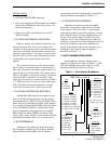
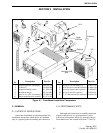
1.2.3 FRONT AND REMOTE MOUNTING
High tier models are available in both front- and
remote-mount versions, and low tier models were
available in a front mount version only. Remote mount
versions are intended to be mounted in a remote loca-
tion up to approximately 17 feet away from the control
unit such as the vehicle’s trunk. Front mount versions
are intended to be mounted within reach of the
operator.
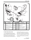
The control unit connects to the remote pigtail
cable coming from the back panel of the transceiver.
This cable is standard with remote mount models and
optional with front mount models. The remote control
unit uses the high tier front panel assembly. A Remote
Conversion Kit is available for converting a front
mount high tier model to remote mounting (see Table
1-3). The transceiver does not have dual-control capa-
bility. Therefore, either the front panel or a remote
control unit can be used for control, but not both.
1.2.4 NPSPAC MODELS (800 MHZ ONLY)
All 800 MHz 988x transceivers capable of oper-
ating on 25 kHz channels meet the stricter specifica-
tions established by NPSPAC (National Public Safety
Panel Advisory Committee) for public safety frequen-
cies from 821-824 and 866-869 MHz. Since deviation
is less on NPSPAC channels, an additional screen is
may be displayed by the tuning software with 800
MHz models for setting NPSPAC deviation. Then
when a public safety channel is selected, the deviation
automatically changes to the level set in this screen.
1.2.5 PROGRAMMING
Transceiver programming is performed using a
PC-compatible computer, the E.F. Johnson Remote
Programming Interface (RPI), and E.F. Johnson
programming software. Programming is described in
separate manuals as described in Section 1.1.1.
1.2.6 TRANSCEIVER ALIGNMENT
Alignment is performed using the standard
Personality programming setup and special Radio
Tune software. There are only two or three adjust-
ments that are made by physically adjusting a compo-
nent on the PC board. All other adjustments are set
digitally. The desired setting is selected using the
computer, and it is then automatically stored in the
transceiver memory. If the manual adjustments do not
need to be readjusted, transceiver alignment can
usually be performed without removing the covers.
Alignment is described in separate manuals as
described in Section 1.1.1.
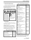
1.3 PART NUMBER BREAKDOWN
The breakdown of the part number used to
identify this transceiver is shown in Table 1-1. With
LTR-Net and Multi-Net models, digits 4-7 of this
number are displayed briefly at power up.
Table 1-1 Part Number Breakdown
242 - 9 8 x x -x x x x
Band
Config.
Freq Range
Signaling
Type
1 = Low tier, dual BW
2 = Mid tier, dual BW*
3 = High tier, dual BW
4 = Low tier, 12.5 kHz
5 = Mid tier, 12.5 kHz*
6 = High tier, 12.5 kHz
8 = High tier rem, dual BW
0 = High tier rem, 12.5 kHz
1 = VHF*
4 = UHF
8 = 800 MHz
9 = 900 MHz
2 = LTR
3 = SMARTNET
4 = Multi-Net
5 = Smartzone
6 = LTR-Net
8 = Data LTR
9 = Data M-Net
0 = Conv only*
0 = Full band (800/
900 MHz)
3 = 430-470 MHz
5 = 470-512 MHz
* These configurations are currently not available
B/N = Comp/Data
C/O = Compander
D/P = Data Cable
E/Q = Enc/Comp
F/T = Enc/Comp/Dat
G/U = Comp/Acsry
H/V = Horn/Acsry
I/W = Enc/Comp/
Acsry Cable
[1] N-W models are
LTR-Net upgradeable
Options [1]
2 =Mid Pwr std
3 = High Pwr std
7 = M.P. no acc
8 = H.P. no acc