


INSTALLATION
2-3
February 2001
Part No. 001-9800-001
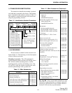
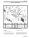
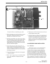
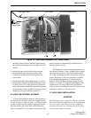
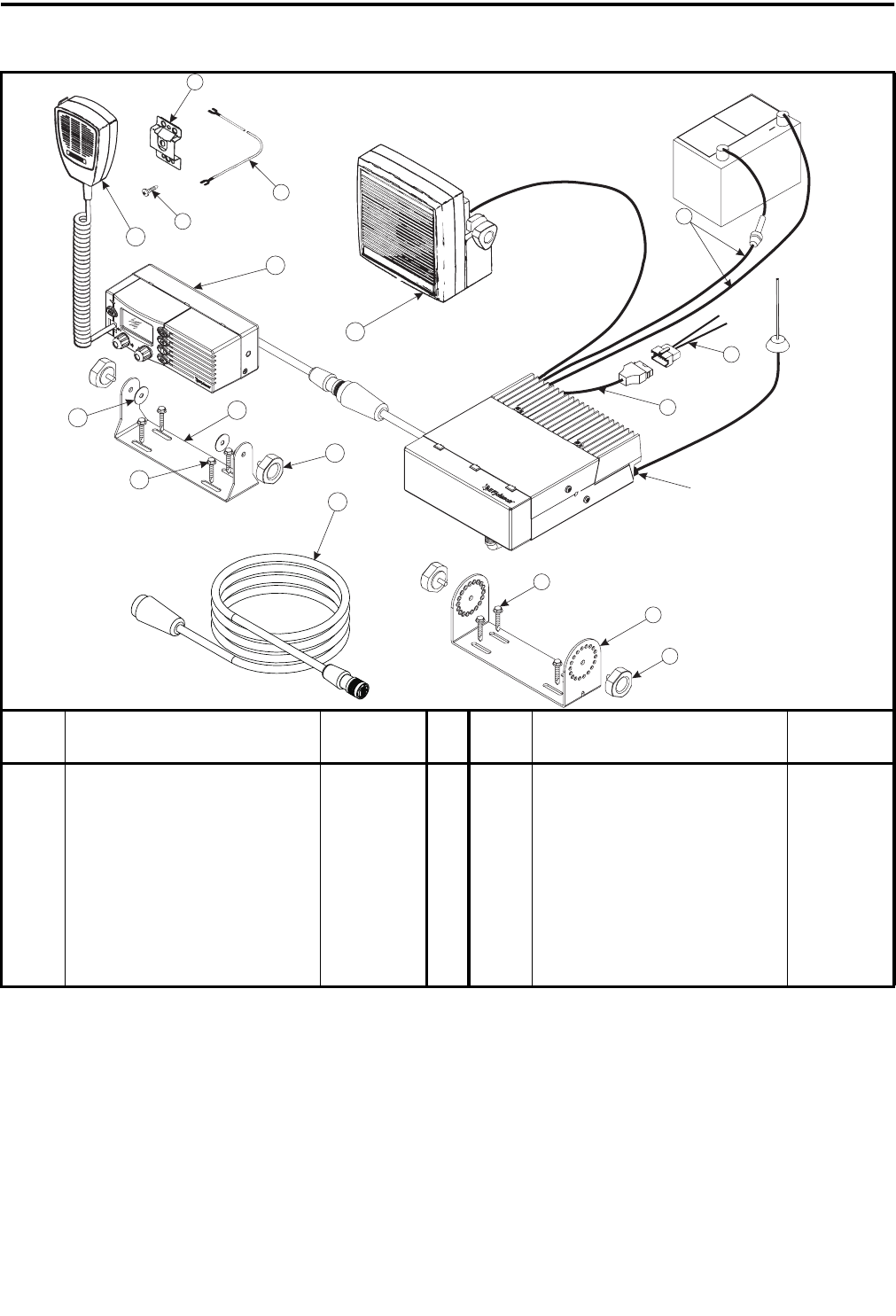
Figure 2-2 Remote Mount Installation Components
Item
No.
Description Part No.
Item
No.
Description Part No.
1 Low profile mounting bracket 017-2229-010 9 Hanger ground wire assembly 023-7171-911
2 Screw, No. 10 self-drilling (4) 575-9077-545 10 Amplified dynamic microphone 250-0740-300
3 Tri-knob (2) 547-0016-008 11 Remote control unit ---
4 Accessory pigtail cable (optional) 597-9800-003 12 Tri-knob (2) 547-0016-008
5 Accessory wire kit (optional) 023-9750-011 13 Mounting bracket, control unit 017-2227-057
6 10-ft. DC power cable & hardware 023-9800-410 14 Screw, No. 10 self-drilling (4) 575-9077-545
22-ft DC power cable & hardware 023-9800-422 15 Flat washer, vulcanized (2) 596-6400-030
7 Microphone hanger 023-3514-001 16 Extension control cable, 11 ft (opt.) 597-9800-009
8 Screw, 4-24 x 5/16” sheet metal (3) 575-3604-010 17 5”, 4.7 ohm external spkr (optional) 250-0151-010
NEG
POS
+
1
2
3
Miniature
UHF Jack
Antenna
4
5
6
7
8
9
10
11
12
13
14
15
17
16
1 ft.
5 ft.
6 ft.
11 ft.
10 or 22 ft.
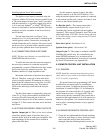
2.3 POWER CABLE INSTALLATION
It is recommended that both wires of the power
cable be connected directly to the vehicle battery.
Connection of either wire to other points may result in
increased interference from the vehicle’s electrical
system. If noise is still a problem with both wires
connected to the battery, a noise filter should be used.
NOTE: With LTR-Net models, do not connect the
power cable to a switched power source such as the
ignition switch or a relay. Always use the front panel
power switch or the ignition sense input described in
Section 2.4.3 to switch power. When power is switched
externally with LTR-Net models, the de-registration
message cannot be sent and the current user settings
are not saved.