


CIRCUIT DESCRIPTION
3-19
February 2001
Part No. 001-9800-001
3.9 TRANSMITTER CIRCUIT DESCRIPTION
(UHF MODELS)
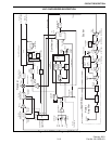
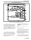
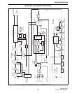
NOTE: A transmitter block diagram is in Figure 3-4.
3.9.1 FIRST AND SECOND AMPLIFIERS
Revised 430-470 MHz and all 470-512 MHz Models
The input signal to the exciter is the transmit
frequency from buffer amplifier Q801 in the synthe-
sizer. It is at a level of approximately 0 dBm and is
applied to first amplifier Q509. Impedance matching
on the input of Q509 is provided by C540, C552,
L503, C550, C551, and L504. Biasing is provided by
R531 and R535, and C526/C527 and C521/C523
decouple RF signals. Impedance matching on the
output is provided by L501, C541, C555, and C556.
Second amplifier Q510 is similar in design to Q509.
These stages together produce about 20 dB of gain.
Power to Q509 is switched on in the transmit
mode by Q506 and Q507. This switch is controlled by
the microcontroller through the Q7 output (pin 11) of
shift register U801. This output is high in the transmit
mode and low in the receive mode. This signal also
controls the antenna switch circuit on the PA board
described in Section 3.9.4.
This transmit 8V supply is not delayed which
allows Q509 and the transmitter frequency to stabilize
before power is produced. The delayed PTT signal is
applied to the RF board on J201, pin 2. This signal
controls the power control circuit described in Section
3.9.6. The emitters of Q505 and Q507 are grounded
through Q508. That transistor is turned off when the
logic is in an undetermined state such as during Flash
programming. This ensures that the transmitter is
turned off during these times.
Unrevised 430-470 MHz Models
The input signal to the exciter is the transmit
frequency from buffer amplifier Q801 in the synthe-
sizer. It is at a level of approximately 0 dBm and is
applied to first amplifier Q506. Impedance matching
on the input of Q506 is provided by C529, C537,
L505, and C530. The input level is set by R528 and
R530. Biasing is provided by R520 and R525, and
C525/C526 and C520/C521 decouple RF signals.
Impedance matching on the output is provided by
L502, C570, C531, L506, and C532. Second amplifier
Q507 is similar in design to Q506. These stages
together produce about 20 dB of gain. The 8-volt
supply to Q506 and Q507 is switched by Q504 similar
to the revised 430-470 MHz version just described.
3.9.2 THIRD AMP AND PREDRIVER
Revised 430-470 MHz and all 470-512 MHz Models
From Q510 the signal is fed to third amplifier
Q511 which is a power MOSFET that provides
approximately 10 dB of gain. Impedance matching
with Q510 is provided by L502, C542, C557. L505,
and C543. Resistors R532 and R534 lower the Q of
the input matching circuit which improves stability.
The gate of Q511 is biased by R527 and R528. Decou-
pling of RF signals is provided by C528/C529 and
C516/C517.
Supply voltage to Q511 is from the power control
circuit described in Section 3.9.6. This circuit varies
the supply voltage to change the power output of Q511
in order to maintain constant transmitter power output.
Impedance matching with between Q511 and
predriver Q512 is provided by several capacitors and
sections of microstrip. Microstrip is a form of trans-
mission line with distributed series inductance and
shunt capacitance. The characteristic impedance is
determined by the width of the microstrip and the PC
board material and thickness (distance from ground
plane).
Class C biasing of Q512 is provided by L506 and
ferrite bead EP2. Several more capacitors and sections
of microstrip on the output of Q512 provide matching
with the 50-ohm input impedance of the power ampli-
fier. This stage provides a gain of approximately 10
dB, resulting in a power input to the PA board of up to
approximately 8 watts.
Unrevised 430-470 MHz Models
From Q507 the signal is fed to third amplifier
Q508 which provides approximately 10 dB of gain.
Impedance matching with Q507 is provided by L503,
C571, C533, C538, L504, L507, C579, and C539.
Biasing is provided by R5542, R555, and R532.
UHF TRANSMITTER DESCRIPTION