


4-1
February 2001
Part No. 001-9800-001
SERVICING
4.1 GENERAL
CAUTION
LTR-Net models may automatically transmit during
normal operation and at power off to send registration
and de-registration messages. Therefore, when a
signal generator is connected to these models, be sure
to use an isolation pad.
4.1.1 PERIODIC CHECKS
This transceiver should be placed on a periodic
maintenance schedule to ensure that it continues to
operate properly. Important checks are receiver sensi-
tivity and transmitter frequency, deviation, and power
output.
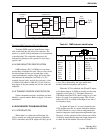
4.1.2 SCHEMATIC DIAGRAMS AND
COMPONENT LAYOUTS
Schematic diagrams and component layouts for
the various PC boards used in this transceiver are
located in the back of this manual. Included are RF
and audio/logic board and interconnect schematics.
The component layouts permit easy location of
components and measurement points. For the RF and
audio/logic boards, a component locator guide and
grid around the boards are provided to aid in locating
components. All boards in this transceiver have
components mounted on one side only. Therefore,
most servicing can be done without removing the
board from the chassis.
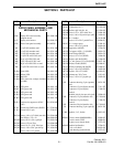
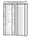
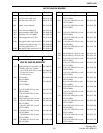
4.1.3 REPLACEMENT PARTS
A replacement parts list for this transceiver is
located in Section 5. The main listing includes the RF
board and chassis parts and another listing includes
the audio/logic board parts. Parts are listed alphanu-
merically according to designator. For information on
ordering parts, refer to Section 1.9. An exploded view
of the transceiver is also included at the end of Section
6 to show the various mechanical parts.
4.1.4 CONFIGURING TRANSCEIVER FOR
TESTING
Multi-Net versions of this transceiver have a test
mode which can be selected to perform testing. This
mode is described in Section 3.13 of the manual listed
in Section 1.1.1, and it permits the transceiver to be
operated manually. To select the test mode, turn power
on with the top two options switches pressed (to right
of display).
LTR-Net and SMARTNET/SmartZone trans-
ceivers do not have a separate test mode that can be
selected to perform testing. With these transceivers,
temporary conventional channels should be
programmed to control the transceiver manually.
If adjustments must be made to the various audio
and data levels, a computer and special tune software
are required. The software and procedure is different
with each operating protocol. Refer to the separate
manual listed in Section 1.1.1 for transceiver align-
ment instructions.
4.2 SURFACE MOUNTED DEVICES (SMDs)
4.2.1 SERVICING TECHNIQUES
Most of the components used in this transceiver
are the surface mounted type. Since these components
and the circuit traces on which they are mounted are
very small in size, special care must be used when
they are replaced. Multi-leaded components such as
integrated circuits must usually be removed using a
heat gun or some other type of heat source that heats
the entire device. Take care so that nearby compo-
nents are not damaged. Surface mounted components
should not be reused since they may be damaged by
the unsoldering process.
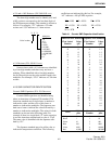
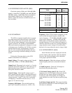
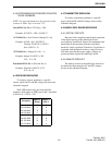
4.2.2 IDENTIFYING SMD RESISTORS
The value of resistors is indicated by a number
printed on the resistor. A three-digit number is used to
identify ±5% and ±10% resistors, and a four-digit
number is used to identify ±1% resistors. Refer to the
following information.
SECTION 4 SERVICING