


3-1
February 2001
Part No. 001-9800-001
CIRCUIT DESCRIPTION
3.1 GENERAL TRANSCEIVER DESCRIPTION
3.1.1 INTRODUCTION
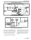
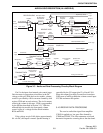
NOTE: A block diagram of the audio and data
processing circuitry on the audio/logic board is
located in Figure 3-3, and block diagrams of the RF
boards are located in Figures 3-4 and 3-7.
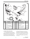
The 9800-series transceivers contain the PC
board assemblies listed below. Components are
mounted on only the top side of all boards. Therefore,
most components can be changed without removing
the board from the chassis.
Audio/Logic - Control logic and audio processing.
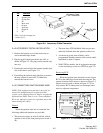
Display - This board contains the LCD display and
controller and interface microcontroller.
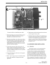
Interface - This small board provides the electrical
connections between the display and audio/logic
boards, and contains the front panel rotary controls
and microphone jack.
RF Board - Receiver, synthesizer, and exciter.
PA Board - Transmitter power amplifier.
General descriptions of the main sections such as
the receiver, synthesizer, and exciter follow, and
detailed descriptions are located in later sections.
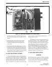
3.1.2 CIRCUIT PROTECTION (FUSES)
Circuit protection is provided by a 15-ampere in-
line power cable fuse, 4-ampere fuse F500 on the RF
board (in the unswitched battery supply line from the
PA board), and by voltage regulators which automati-
cally limit current. The 15-ampere power cable fuse
protects the power amplifier module and final stages
on the power amplifier board, and the 4-ampere fuse
protects the remainder of the circuitry. In addition,
there are two fuses on the audio/logic board. One fuse
(F100, 2A) limits the current of the switched battery
supply fed to accessory connector J101, the micro-
phone jack, and also the display board. The other fuse
(F300, 0.6A) limits the current of the 8-volt supply fed
to modem jack J301. For information on power distri-
bution and switching, refer to Section 3.2.
3.1.3 SYNTHESIZER
The synthesizer output signal is the transmit
frequency in the transmit mode and the receive first
injection frequency in the receive mode. The synthe-
sizer also provides the receiver second injection signal
by tripling the TCXO frequency.
Channels are selected by programming the main
divider in synthesizer integrated circuit U804 to divide
by a certain number. This programming is provided by
microcontroller U101 on the audio/logic board. The
minimum frequency resolution is 6.25 or 10 kHz. The
frequency stability of the synthesizer is determined by
the stability of TCXO U806 (Temperature Compen-
sated Crystal Oscillator). The TCXO has a frequency
stability of ± 2.0 PPM (UHF) or ± 1.5 PPM (800/900
MHz) from –22° to +140° F (–30 to +60° C).
3.1.4 AUDIO/LOGIC BOARD
Microcontroller U101 on the audio/logic board
provides transceiver control functions including
synthesizer programming, system and group scan,
data encoding and decoding, squelch, and gating of
audio and data signals. The audio/logic board also has
analog circuitry which provides filtering, amplifica-
tion, and other processing of the audio, data, and Call
Guard signals.
The U101 operating program is stored in Flash
EPROM U108. This type of memory can be repro-
grammed in the field using the standard programming
setup and special programming software. This allows
the operating software to be easily updated without the
need to change a microprocessor or EPROM. Flash
EPROM memory devices retain data indefinitely
without the need for battery backup, and can be repro-
grammed many times.
Parameters which change from transceiver to
transceiver such as programmed system and groups
and option key programming are also stored in the
SECTION 3 CIRCUIT DESCRIPTION