


INSTALLATION
2-2
February 2001
Part No. 001-9800-001
2.1.3 TRANSCEIVER PROGRAMMING
The transceiver needs to be programmed before it
is placed in service unless it was ordered as factory
programmed. Programming instructions are located in
the manuals listed in Section 1.1.1. Transceivers are
normally shipped with preprogrammed factory test
channels and test parameters.
2.1.4 REQUIRED POWER SOURCE
This transceiver is designed for installation in
vehicles which have a nominal 12-volt, negative
ground electrical system (negative battery terminal
connected directly to the chassis). If the vehicle has
some other type of electrical system, a voltage
converter is required.
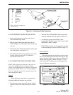
2.2 MOUNTING THE TRANSCEIVER
2.2.1 SELECTING A MOUNTING LOCATION
Front mount transceivers are designed for
mounting in a location within convenient reach of the
operator such as the dash, console, or floor. Remote
mount models are designed for mounting in a remote
location such as under a seat or in the trunk that is up
to 6 feet (or up to 17 feet with optional extension
cable) from the control unit.
WAR NI NG
The mounting location of the transceiver or control
unit can affect safe operation of the vehicle. Follow
these precautions when mounting this transceiver:
• Mount it where it does not interfere with operation
of the vehicle controls.
• Mount it where the operator can easily see the
display and reach the controls.
• Mount it where it will be least likely to cause injury
in case of an accident.
• Airbags deploy with great force. Therefore, do not
mount it anywhere near the deployment area. In
addition, do not place any other objects in the
deployment area.
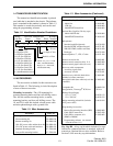
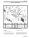
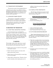
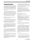
2.2.2 INSTALLATION COMPONENTS
The following mounting kits are used to install
the transceiver. These components and other compo-
nents are shown in Figure 2-1.
Mounting Kit, Part No. 023-9800-030
• Two tri-knobs for attaching the transceiver to the
mounting bracket
• Four No. 10 self-drilling screws
Universal Cable and Hardware Kit
Part No. 023-9800-410 (10 ft)
Part No. 023-9800-422 (22 ft)
• 10 ft or 22 ft fused power cable
• Microphone clip and ground wire
• One 7A and one 15A fuse (7A not used)
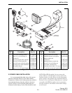
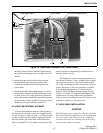
2.2.3 ATTACHING MOUNTING BRACKET
Either Standard Mounting Bracket, Part No. 017-
2229-005, or Low Profile Mounting Bracket, Part No.
017-2229-010, can be used to mount the transceiver.
Proceed as follows:
1. Check the area underneath the selected mounting
surface for such things as wires, electrical compo-
nents, and brake and gas lines that could be
damaged when the mounting bracket screws are
installed. Then install the mounting bracket using
the included self-tapping screws or other screws if
desired.
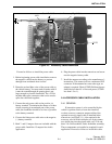
2. Install the transceiver in the bracket using the
included knobs.
3. With front mount transceivers, install the included
microphone hanger in a convenient location using
the included sheet metal screws or others. For
proper operation of functions such as the monitor
mode and scan, the hanger must be connected to
chassis ground. If required, ground the hanger using
the included ground wire.