


CIRCUIT DESCRIPTION
3-17
February 2001
Part No. 001-9800-001
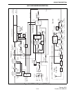
CR202. The function of this filter is to attenuate
frequencies outside the receive band such as the first
injection, image, and half IF frequencies. The pass-
band frequency of the filter is shifted in four steps
using PIN diodes. These diodes are controlled by
microcontroller through the Q2 and Q3 outputs of shift
register U800. The control signals for each of four
band segments are listed in Section 4.4.
The PIN diodes present a very low impedance at
RF frequencies when forward biased and a very high
impedance when reverse biased. This allows them to
be used to switch capacitance in and out of the filter.
For example, when the lowest segment of the
frequency band is selected, both control signals are
high and the diodes are forward biased by current
flowing through R201-R204. Therefore, C207, C208,
C218, and C219 are effectively connected to ground
through CR201 and CR202 which lowers the passband
frequency of the filter.
Ceramic resonators L200 and L201 have a very
high Q and therefore cause very little receive signal
loss. Capacitors on the input and output of the filter
provide impedance matching with the adjoining
stages.
3.8.2 RF AMPLIFIER (Q201)
RF amplifier Q201 improves and stabilizes
receiver sensitivity and also recovers filter losses.
Several capacitors on the input and also L202 provide
impedance matching. CR203 protects the base-emitter
junction of Q201 from damage caused by high level
input signals.
The bias current of Q201 is fixed at a constant
level by Q200. The collector current of Q201 flows
through R207. The voltage drop across that resistor
(and therefore the current) is set by R205 and R206.
For example, if current through R207 attempts to
increase, the emitter voltage of Q200 decreases. Q200
then conducts less and turns Q201 off slightly to main-
tain a constant bias current. This provides a stable bias
over changes in temperature.
The output signal of Q201 is fed to another two-
pole bandpass filter similar to the one on the input of
Q201 as described in the preceding section. Imped-
ance matching with the filter is provided by L203,
C227, C228, C234, and C235. Resistor R209 lowers
the Q of L203 to make it less frequency selective.
C222-C226 decouple various unwanted AC signals
from the circuit.
3.8.3 FIRST MIXER (Q202), INJECTION
AMPLIFIER (Q204)
Q202 is a dual-gate MOSFET mixer. Impedance
matching at one gate is provided by C245, R214, and
L207. The first injection frequency from the synthe-
sizer is applied to the other gate. Since the first IF is 45
MHz and low-side injection is used, the injection
frequency is 45 MHz below the receive frequency.
The signal from the synthesizer is amplified by
Q204. A 3 dB pad on the output, consisting of R225-
R227, sets the input level to the mixer. A low-pass
filter network formed by C262-C264 and L211 attenu-
ates spurious frequencies occurring above the injection
frequency band. Q203 provides a stable bias current
similar to Q200 described in Section 3.8.2. Tempera-
ture compensation is provided by CR206 which
mirrors the voltage drop across the base-emitter junc-
tion of Q204.
Impedance matching on the output of mixer Q202
is provided at 45 MHz by L208, C251, and C252. The
signal is then fed to Z204 which is a four-pole crystal
filter with a nominal –3 dB bandwidth of 15 kHz. This
filter attenuates wideband noise, adjacent channels,
frequencies resulting from intermodulation, and other
undesired frequencies. Impedance matching on the
input is provided by C251, C252, C266, C268, and
L213; impedance matching on the output is provided
by C270, C271, C272, L215, and R228.
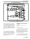
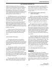
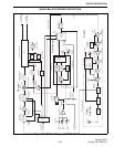
3.8.4 SECOND MIXER/DETECTOR (U201)
Second Mixer
U201 contains second mixer, IF amplifier,
detector, RSSI, and audio amplifier stages as shown in
Figure 3-6. The 45 MHz IF signal is applied to pin 2
which is the input of an internal IF amplifier stage.
From the IF amplifier the signal is internally fed to the
mixer which combines it with the 44.550 MHz second
injection frequency to produce a second IF of 450
kHz.
UHF RECEIVER DESCRIPTION