


CIRCUIT DESCRIPTION
3-10
February 2001
Part No. 001-9800-001
frequencies below 300 Hz that could cause interfer-
ence with LTR data and Call Guard signals.
Gate U308B blocks the microphone signal when
microphone audio is not transmitted such as during the
data handshake to set up the call. A high signal on pin
5 closes the gate and passes the signal. This gate is
controlled by the Q6 output (pin 13) of latch U110.
Transistor Q307 functions as an inverter and level
translator.
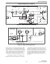
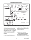
3.5.2 SUMMING AMPLIFIER (U303D), PRE-
EMPHASIS/LIMITER (U303A)
U303D amplifies the transmit audio signal and
also the transmit data signal from an optional modem
if one is used. Jumper R398 is installed to route the
modem signal to U303D and the filtering circuitry, or
jumper R399 is installed to route a wideband signal
directly to the synthesizer so that it bypasses the
filtering circuitry. U308A closes when wideband (25
kHz) channels are selected. This bypasses R403 which
provides a higher deviation level with those channels.
NOTE: If the wideband data input is used, the external
device must provide FCC-approved modulation
limiting and splatter filter circuitry and a stable DC
level.
The output signal from U303D is then routed via
the option wireouts to U303A which provides limiting
and 6 dB per octave pre-emphasis. This stage is an
amplifier which limits by saturating. Limiting prevents
over-modulation caused by high-level input signals.
R370 and R378 set the input level to the next stage,
and C334 provides DC blocking.
3.5.3 SPLATTER FILTER (U302B, U302C)
U302B and U302C form a five-pole, low-pass
splatter filter which attenuates frequencies above
3 kHz. This prevents adjacent channel interference.
Frequencies over 3 kHz may be produced if limiting
occurs in the limiter stage just described. The signal is
then fed to digital potentiometer U802 on the RF
board which sets the deviation level. Refer to Section
3.7.4 for more information.
3.5.4 TRANSMIT DATA CIRCUIT (U302D,
U302A)
The transmit LTR data and Call Guard tone/data
signals are generated by the microcontroller on pins 37
and 38. The four logic combinations possible with
these two outputs are applied to a resistor network
consisting of R389, R392, R386, and R395. This
network creates a four-step pseudo sine wave from the
digital outputs. This signal is applied to a low-pass
filter formed by U302D and U302A. This filter attenu-
ates harmonics present in the signal which provides
smoothing of the stepped sine wave.
The passband of this filter is controlled by Q306
which switches additional capacitance into the circuit.
When LTR or digital Call Guard data or low-
frequency tone Call Guard signaling is being trans-
mitted, Q306 is turned on and the cut-off frequency
decreases to approximately 150 Hz. Then when a
high-frequency tone Call Guard signal is being trans-
mitted, Q306 is turned off and the cut-off frequency
increases to approximately 220 Hz. Q306 is controlled
by the same signal used to control Q300 in the receive
data circuit (see Section 3.4.3).
U308C provides gating of the transmit data
signal. When the control input (pin 6) is high, the gate
is closed and the signal is passed. Test gate U307A is
used in the test mode to bypass the data filter to
provide the wideband data signal required for setting
modulation balance. Q303 and Q308 provide level
translation and inversion. The transmit data signal is
then fed to digital potentiometer U802 on the RF
board which sets the data deviation level. Refer to
Section 3.7.4 for more information.
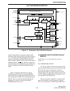
3.6 DISPLAY BOARD
Control of most display board functions is
provided by microcontroller U2. This device contains
a 2K byte ROM and 128 byte RAM and has 20 I/O
lines. It communicates with microcontroller U101 on
the audio/logic board via the SPI serial bus consisting
of SCK, MOSI, and MISO lines (see Section 3.3.1).
When there is data to send to the audio/logic board,
such as if an option switch is pressed, U2 issues a
service request on the Service Request Out line (J1,
pin 6).
AUDIO/LOGIC DESCRIPTION (ALL MODELS)